3UG4622-1AW30 SIEMENS, 3UG4622-1AW30 Datasheet - Page 112
3UG4622-1AW30
Manufacturer Part Number
3UG4622-1AW30
Description
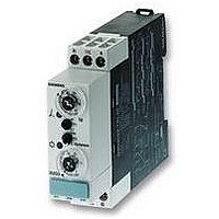
RELAY, MONITOR, 22.5MM
Manufacturer
SIEMENS
Series
3UG46r
Datasheet
1.3UG4622-1AW30.pdf
(114 pages)
Specifications of 3UG4622-1AW30
Contact Configuration
SPCO
Power Consumption
4VA
Supply Voltage Max
240VAC
Contact Current Max
3A
Relay Mounting
DIN Rail
Coil Voltage Vac Nom
230V
External Depth
86mm
Coil Frequency Max
60Hz
Coil Operating Frequency Min
50Hz


■
■
3RS17 interface converters
Overview
Interface converters perform the coupling function for analog
signals on both the input side and the output side. They are
indispensable when processing analog values with electronic
controls. Under harsh industrial conditions in particular, it is often
necessary to transmit analog signals over long distances. This
means that electrical isolation is essential due to the different
supply systems. The resistance of the wiring causes potential
differences and losses which must be prevented.
Function
Active interface converters
Active interface converters provide maximum flexibility for the
application by the use of an external supply voltage.
Configuration with active interface converters is extremely easy
because input and output resistances and voltage drops are
compensated by the auxiliary supply. They support complete
voltage isolation as well as conversion from one signal type to
another or reinforcement. The load of the measured value
transmitter is negligible.
Passive interface converters
Passive interface converters do not require an external supply
voltage. This advantage can only be used by current signals that
are converted 1:1. Reinforcement or conversion is not possible.
The converters are used for complete electrical isolation of
current signals and to protect the inputs and outputs. Passive
isolators do not operate reaction-free, any load on the output
produces an equal load on the input. When the passive
converter is to be used, the output performance of the sensor
and the input resistance of the analog input must be analyzed.
This technique is being increasingly implemented in the case of
pure current signals.
Calculation guide for passive converters
Note: Please note the following when using passive isolators:
The current-driving voltage of the measuring transducer U
be sufficient to drive the maximum current of 20 mA over the
passive isolator with a voltage loss of U
This means that:
U
Distribution of the voltages in the case of passive isolators
7/112
B
˜ U
7
E
Interface Converters
= 2.7 V + 20 mA × R
1
Siemens LV 1 T · 2006
1
7
B
7
1
1
V
= 2.7 V and the load R
4
E
must
B
.
Electromagnetic disturbance and overvoltages can affect the
signals on the input side in particular or even destroy the analog
modules. All terminals of the 3RS17 interface converters are safe
up to a voltage of 30 V DC and protected against switching
poles. Short-circuit protection is an especially important function
for the outputs.
The devices are EMC-tested according to
• EN 50081 (basic technical standard for emitted interference)
• EN 61000-6-2 (basic technical standard for immunity to
The analog signals comply with
• IEC 60381-1/2
Input voltage depending on the load at I
The following diagram shows the input voltage U
of the load R
is known, the y-axis shows the minimum voltage that has to be
supplied by the current source in order to drive the maximum
current of 20 mA over the passive isolator and load.
Current carrying capacity of the outputs
A maximum output resistance is specified for current signals.
This resistance value specifies how large the input resistance of
the next device connected in series can be as a result of the
power of the converter.
For voltage signals, the maximum current that can be drawn
from the output is the decisive factor.
2-way isolation
In the case of 2-way isolation, the input is galvanically isolated
from the output. The "null potential" of the supply voltage is the
same as the reference potential for the analog output signal.
3-way isolation
For the 3-path isolation, each circuit is electrically isolated from
the other circuits, i.e. input, output, and supply voltage do not
have a potential connection.
interference)
7
B
taking into account the voltage loss U
a
= 20 mA
E
as a function
V
. If the load
7
4
O
Related parts for 3UG4622-1AW30
Image
Part Number
Description
Manufacturer
Datasheet
Request
R

Part Number:
Description:
RELAY, DIGITAL MONITORING, CURRENT
Manufacturer:
SIEMENS
Datasheet:

Part Number:
Description:
Intel 80C32 - Siemens SAB-C501, Nearest Equivalent Replacement
Manufacturer:
Siemens Semiconductor Group
Part Number:
Description:
IGBT MODULE
Manufacturer:
Siemens Semiconductor Group
Datasheet:
Part Number:
Description:
SIMOPAC Module (Power module Single switch N channel Enhancement mode)
Manufacturer:
Siemens Semiconductor Group
Datasheet:
Part Number:
Description:
(BSMxxx) TRANSISTOR
Manufacturer:
Siemens Semiconductor Group
Datasheet:
Part Number:
Description:
SIMOPAC Module (Power module Single switch N channel Enhancement mode)
Manufacturer:
Siemens Semiconductor Group
Datasheet:
Part Number:
Description:
main ratings
Manufacturer:
Siemens Semiconductor Group
Datasheet:
Part Number:
Description:
Manufacturer:
Siemens Semiconductor Group
Datasheet:
Part Number:
Description:
Manufacturer:
Siemens Semiconductor Group
Datasheet:
Part Number:
Description:
Manufacturer:
Siemens Semiconductor Group
Datasheet:
Part Number:
Description:
ICs for Consumer Electronics
Manufacturer:
Siemens Semiconductor Group
Datasheet:
Part Number:
Description:
Video and Sound IF with V & S SCART
Manufacturer:
Siemens Semiconductor Group
Datasheet:
Part Number:
Description:
Manufacturer:
Siemens Semiconductor Group
Datasheet:
Part Number:
Description:
Multistandard Sound IF
Manufacturer:
Siemens Semiconductor Group
Datasheet: