S2-L2-24VDC PANASONIC EW, S2-L2-24VDC Datasheet - Page 4
S2-L2-24VDC
Manufacturer Part Number
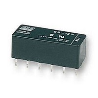
S2-L2-24VDC
Description
POWER RELAY DPST-NO/NC 24VDC 4A PC BOARD
Manufacturer
PANASONIC EW
Datasheet
1.S2-12VDC.pdf
(5 pages)
Specifications of S2-L2-24VDC
Relay Type
Latching
Coil Voltage Vdc Nom
24V
Contact Current Max
4A
Contact Voltage Ac Nom
250V
Contact Voltage Dc Nom
30V
Coil Resistance
2850ohm
Lead Free Status / RoHS Status
Lead free / RoHS Compliant


S
8. Effect from an external magnetic field
ACCESSORIES
Dimensions
Inserting and removing method
Inserting method: Insert the relay as
shown in Fig. 1 unit the rib of the relay
snaps into the clip of the socket.
Removing method:
(1) Remove the relay straight from the
socket holding the shaded portion of the
relay as shown in Fig. 2.
(2) When sockets are mounted in close
proximity, use a slotted screw driver as
shown in Fig. 3.
4
.720±.024
.488±.024
18.3±0.6
.191±.012
12.4±0.6
.047±.012
4.85±0.3
+30
+30
–30
–30
1.2±0.3
0
0
.059±.012
Single side stable
2 coil latching
1.5±0.3
1.276±.024
.200±.012
5.08±0.3
32.4±0.6
S Relay Socket,
S-PS
50
50
Drop-out voltage
G
G
Pick-up voltage
Pick-up voltage
.059±.012
1.5±0.3
.610±.024
15.5±0.6
100
100
Terminal width: 1.3
Terminal thickness: 1.2
.300±.012
7.62±0.3
Specifications
(Note: Don't insert or remove relays while in the energized condition.)
Breakdown voltage
Insulation resistance
Heat resistance
Maximum continuous current
+30
–30
+30
–30
.016±.004
0.4±0.1
0
0
.134±.012
Single side stable
2 coil latching
3.4±0.3
.051
.047
Rib
50
50
Fig. 3
G
G
Drop-out voltage
Pick-up voltage
Pick-up voltage
Fig. 1
Fig. 2
More than 100 MΩ between terminals at 500 V DC Mega
100
100
PC board pattern (Copper-side view)
12-.063 DIA. HOLE
12-1.6 DIA. HOLE
150 ±3°C
1,500 Vrms between terminals
.299
7.6
(302
.200
5.08
.200
5.08
en_ds_61105_0000: 130804D
4 A
±5.4°F) for 1 hour.
.200
5.08
.200
5.08
5.08
.200
mm
inch
Related parts for S2-L2-24VDC
Image
Part Number
Description
Manufacturer
Datasheet
Request
R

Part Number:
Description:
RELAY, PCB, DPNO & DPNC
Manufacturer:
PANASONIC EW
Datasheet:
Part Number:
Description:
RELAY, PCB, DPNO & DPNC
Manufacturer:
PANASONIC EW
Datasheet:


Part Number:
Description:
POWER RELAY, 24VDC, 30A, SPST-NO
Manufacturer:
PANASONIC EW
Datasheet:

Part Number:
Description:
POWER RELAY, SPDT, 12VDC, 10A, PC BOARD
Manufacturer:
PANASONIC EW

Part Number:
Description:
POWER RELAY, 24VDC, 5A, SPST-NO, PCB
Manufacturer:
PANASONIC EW
Datasheet:


Part Number:
Description:
SIGNAL RELAY, DPDT, 4.5VDC, 1A, SMD
Manufacturer:
PANASONIC EW
Datasheet:

Part Number:
Description:
SIGNAL RELAY, DPDT, 4.5VDC, 1A, THD
Manufacturer:
PANASONIC EW
Datasheet:

Part Number:
Description:
MINIATURE RELAY, DPDT, 24VDC, 2A, THD
Manufacturer:
PANASONIC EW

Part Number:
Description:
SIGNAL RELAY, DPDT, 5VDC, 2A, PC BOARD
Manufacturer:
PANASONIC EW
Datasheet:


Part Number:
Description:
PHOTOMOS RELAY, 60VDC, 400mA
Manufacturer:
PANASONIC EW
Datasheet:

Part Number:
Description:
PHOTOMOS RELAY, 400V, 150mA
Manufacturer:
PANASONIC EW
Datasheet: