S2-L2-24VDC PANASONIC EW, S2-L2-24VDC Datasheet - Page 5
S2-L2-24VDC
Manufacturer Part Number
S2-L2-24VDC
Description
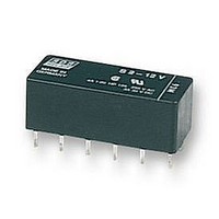
POWER RELAY DPST-NO/NC 24VDC 4A PC BOARD
Manufacturer
PANASONIC EW
Datasheet
1.S2-12VDC.pdf
(5 pages)
Specifications of S2-L2-24VDC
Relay Type
Latching
Coil Voltage Vdc Nom
24V
Contact Current Max
4A
Contact Voltage Ac Nom
250V
Contact Voltage Dc Nom
30V
Coil Resistance
2850ohm
Lead Free Status / RoHS Status
Lead free / RoHS Compliant


NOTES
1. Special use of 2 coil latching types: 2
ways can be considered if 2 coil latching
types are used as 1 coil latching types.
(A) Reverse polarity is applied to the set
coil of 2 coil latching type.
(B) By shorting terminals 12 and 7, apply
plus to 1, minus to 6 at set and plus to 6,
minus to 1 at reset. Applied coil voltage
should be the same as the nominal.
Operating power will be reduced to one-
half.
CAUTIONS FOR USE
Based on regulations regarding insulation distance, there is a
restriction on same-channel load connections between terminals
No. 2, 3 and 4, 5, as well as between No. 8, 9 and 10, 11. See
the figure below for an example.
For Cautions for Use, see Relay Technical Information (see catalog).
en_ds_61105_0000: 130804D
Reset position of 2a2b type
-
12
1
11
2
10
3
4
9
Between 2, 3 and 4, 5:
Between 10, 11 and 8, 9:
5
8
6
11
7
+
2 3
10
No good
different channels, therefore not possible
different channels, therefore not possible
9
4
5
2. Soldering operations should be
accomplished as quick as possible;
within 10 seconds at 250°C
temperature or 3 seconds at 350°C
662°F. The header portion being sealed
with epoxy resin, undue subjection to
heat may cause loss of seal. Solder
should not be permitted to remain on the
header.
8
Between 2, 3 and 4, 5:
Between 10, 11 and 8, 9:
11
2
10
3
Good
same channels, therefore possible
same channels, therefore possible
482°F
4
9
5
8
solder
S
5
Related parts for S2-L2-24VDC
Image
Part Number
Description
Manufacturer
Datasheet
Request
R

Part Number:
Description:
RELAY, PCB, DPNO & DPNC
Manufacturer:
PANASONIC EW
Datasheet:
Part Number:
Description:
RELAY, PCB, DPNO & DPNC
Manufacturer:
PANASONIC EW
Datasheet:


Part Number:
Description:
POWER RELAY, 24VDC, 30A, SPST-NO
Manufacturer:
PANASONIC EW
Datasheet:

Part Number:
Description:
POWER RELAY, SPDT, 12VDC, 10A, PC BOARD
Manufacturer:
PANASONIC EW

Part Number:
Description:
POWER RELAY, 24VDC, 5A, SPST-NO, PCB
Manufacturer:
PANASONIC EW
Datasheet:


Part Number:
Description:
SIGNAL RELAY, DPDT, 4.5VDC, 1A, SMD
Manufacturer:
PANASONIC EW
Datasheet:

Part Number:
Description:
SIGNAL RELAY, DPDT, 4.5VDC, 1A, THD
Manufacturer:
PANASONIC EW
Datasheet:

Part Number:
Description:
MINIATURE RELAY, DPDT, 24VDC, 2A, THD
Manufacturer:
PANASONIC EW

Part Number:
Description:
SIGNAL RELAY, DPDT, 5VDC, 2A, PC BOARD
Manufacturer:
PANASONIC EW
Datasheet:


Part Number:
Description:
PHOTOMOS RELAY, 60VDC, 400mA
Manufacturer:
PANASONIC EW
Datasheet:

Part Number:
Description:
PHOTOMOS RELAY, 400V, 150mA
Manufacturer:
PANASONIC EW
Datasheet: