NC2D JP 12VDC PANASONIC EW, NC2D JP 12VDC Datasheet - Page 3
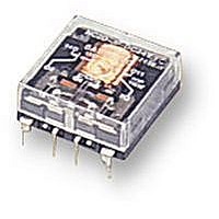
NC2D JP 12VDC
Manufacturer Part Number
NC2D JP 12VDC
Description
RELAY, PCB, DPCO, 12VDC
Manufacturer
PANASONIC EW
Datasheet
1.NC2D_JP_12VDC.pdf
(11 pages)
Specifications of NC2D JP 12VDC
Relay Type
General Purpose
Coil Voltage Vdc Nom
12V
Contact Current Max
5A
Contact Voltage Ac Nom
250V
Coil Resistance
400ohm
Coil Type
DC Coil, Monostable
Nom Operating Power
360mW
Relay Mounting
PC
Contact Configuration
DPCO
Rohs Compliant
Yes
Lead Free Status / RoHS Status
Lead free / RoHS Compliant


4 Form C 2 coil latching
Notes:
1. Two coil latching relay 4C series are for intermittent operation only. Power should
2. Coil resistance is the measured value at a coil temperature of 20°C. Compensate
DIMENSIONS
Flat series
2C single side stable
(NC2D-JP)
(NC2EBD-JP)
2C 2 coil latching
(NC2D-JPL2)
(NC2EBD-JPL2)
en_ds_61135_0000: 310105J
NC4D-JPL2-DC5V
NC4D-JPL2-DC6V
NC4D-JPL2-DC12V
NC4D-JPL2-DC24V
NC4D-JPL2-DC48V
NC4D-JPL2-DC110V
be applied to coil continuously for no more than two minutes.
coil resistance by plus or minus 0.4% for each degree (°C) of coil temperature
change.
PC board terminal
Flat series
NC4D-L2-DC5V
NC4D-L2-DC6V
NC4D-L2-DC12V
NC4D-L2-DC24V
NC4D-L2-DC48V
NC4D-L2-DC110V
5.08
.200
Plug-in
7.62
.300
5.08
.200
2.54
.100
5.08
.200
1.000
1.000
25.4
5.08
.200
.200
5.08
25.4
5.08
.200
5.08
.200
5.08
.200
7.62
.300
5.08
.200
2.54
.100
Vertical series
Standard type
Standard type
5.08
.200
NC4D-PL2-DC5V
NC4D-PL2-DC6V
NC4D-PL2-DC12V
NC4D-PL2-DC24V
NC4D-PL2-DC48V
NC4D-PL2-DC110V
PC board terminal
1.000
1.000
25.4
25.4
General tolerance: ±0.5
General tolerance: ±0.5
10.9
.429
10.9
.429
27.94
1.100
3.5
.138
27.94
1.100
3.5
.138
Pick-up voltage
(max.)
5.08
.200
19.2
38.4
88.0
4.0
4.8
9.6
7.62
.300
5.08
.200
2.54
.100
5.08
.200
1.000
25.4
±.020
1.000
±.020
5.08
.200
5.08
.200
3. “Maximum allowable voltage” is that value at maximum contact rating and
25.4
5.08
.200
5.08
.200
Amber sealed type
Amber sealed type
maximum ambient temperature. The graph shown in the data describes the inter-
relationship; care should be taken to prevent the total of ambient temperature and
the coil temperature rise from exceeding 120°C.
5.08
.200
7.62
.300
5.08
2.54
.100
.200
Coil voltage, V DC
5.08
.200
Reset voltage
(max.)
19.2
38.4
88.0
4.0
4.8
9.6
1.000
25.4
1.000
25.4
10.9
.429
10.9
.429
allowable voltage
(within 2 min.)
27.94
1.100
3.5
.138
3.5
.138
Maximum
27.94
1.100
13.2
26.4
52.8
121
5.5
6.6
Diagram shows the “reset” position
when terminals 3 and 6 are energized.
Energize terminals 4 and 5 to transfer
contacts.
PC board pattern (Copper-side view)
PC board pattern (Copper-side view)
Coil resistance,
2.54
.100
2.54
.100
27.94
1.100
27.94
1.100
Schematic (Top view)
Deenergized position
Schematic (Top view)
Ω (±10%)
1,440
7,560
15.6
22.5
360
2.54
.100
90
2
2 3
14 13 12
7
14 13 12
7
11
11 12 13 14
– –
2.54
.100
Tolerance: ±0.1
Tolerance: ±0.1
4
–
4
12 13 14
5
5
10-1.2 DIA. HOLES
10-.047 DIA. HOLES
8-1.2 DIA. HOLES
8-.047 DIA. HOLES
.020
+
0.5
+
5
5
4
4
6
+
11
11
operating power,
7
7
2
2
Nominal
1,600
mW
mm
NC
±.004
±.004
inch
3
Related parts for NC2D JP 12VDC
Image
Part Number
Description
Manufacturer
Datasheet
Request
R

Part Number:
Description:
POWER RELAY, DPDT, 12VDC, 5A, PC BOARD
Manufacturer:
PANASONIC EW
Datasheet:
Part Number:
Description:
POWER RELAY, DPDT, 24VDC, 5A, PC BOARD
Manufacturer:
PANASONIC EW
Datasheet:

Part Number:
Description:
RELAY, PCB, DPCO, 24VDC
Manufacturer:
PANASONIC EW
Datasheet:
Part Number:
Description:
POWER RELAY, DPDT, 5VDC, 5A, PC BOARD
Manufacturer:
PANASONIC EW
Datasheet:

Part Number:
Description:
RoHS Compliant:Yes
Manufacturer:
PANASONIC EW
Datasheet:

Part Number:
Description:
RELAY POWER 5A 24VDC VERT PLUGIN
Manufacturer:
Panasonic Electric Works
Datasheet:

Part Number:
Description:
RELAY POWER 5A 12VDC VERT PLUGIN
Manufacturer:
Panasonic Electric Works
Datasheet:

Part Number:
Description:
RELAY PWR VERT DPDT 5A 12VDC
Manufacturer:
Panasonic Electric Works
Datasheet:
Part Number:
Description:
RELAY DPDT 5A 5VDC VERT PC MNT
Manufacturer:
Panasonic Electric Works
Datasheet:
Part Number:
Description:
RELAY POWER 5A 5VDC VERT PLUG-IN
Manufacturer:
Panasonic Electric Works
Datasheet:

Part Number:
Description:
SIGNAL RELAY, DPDT, 5VDC, 2A, PC BOARD
Manufacturer:
PANASONIC EW
Datasheet:


Part Number:
Description:
PHOTOMOS RELAY, 60VDC, 400mA
Manufacturer:
PANASONIC EW
Datasheet:

Part Number:
Description:
PHOTOMOS RELAY, 400V, 150mA
Manufacturer:
PANASONIC EW
Datasheet: