NC2D JP 24VDC PANASONIC EW, NC2D JP 24VDC Datasheet - Page 11
NC2D JP 24VDC
Manufacturer Part Number
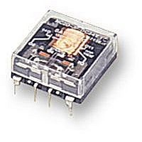
NC2D JP 24VDC
Description
RELAY, PCB, DPCO, 24VDC
Manufacturer
PANASONIC EW
Datasheet
1.NC2D_JP_12VDC.pdf
(11 pages)
Specifications of NC2D JP 24VDC
Relay Type
General Purpose
Coil Voltage Vdc Nom
24V
Contact Current Max
5A
Contact Voltage Ac Nom
250V
Coil Resistance
1.6kohm
Coil Type
DC Coil, Monostable
Nom Operating Power
360mW
Relay Mounting
PC
Contact Configuration
DPCO
Rohs Compliant
Yes
Lead Free Status / RoHS Status
Lead free / RoHS Compliant


NC4-SS
NC4-L2S
NC4-PS
NC4-L2P
NOTES
1. To maintain insulation between coils of
2 coil latching series, terminals 5 and 6
for flat series, and terminals 3 and 4 for
slim series should be connected to
provide common return.
2. 2 coil latching series 4C are for
intermittent operation only. Power should
be applied to coils continuously for no
more than two minutes.
3. When designing printed circuit board
patterns, note that:
(1) “Top View” wiring diagram is indicated
for the Flat series because terminals can
be seen from above.
For Cautions for Use, see Relay Technical Information (see catalog).
en_ds_61135_0000: 310105J
Set switch
Set coil
5
4
6
Reset coil
3
Reset switch
1.732
44.0
1.732
44.0
Terminal width: 1.9
Terminal thickness: 0.4
Terminal width: 0.9
Terminal thickness: 0.4
12.6
.496
12.6
.496
Terminals 3 and 6 excluded for NC4-SS.
Terminals 3 and 6 excluded for NC4-PS.
20.4
.803
.154
20.4
.803
.154
(2) “Bottom View” wiring diagram is
indicated for the Slim series because
terminals can not be seen from above.
4. When using slim series in close
proximity, mount all relays facing the
same direction.
Different mounting directions may cause
change in the relay characteristics
because NC relays are polarized.
3.9
3.9
.075
.035
.339
8.6
.039
1.0
.339
.039
8.6
1.0
.016
.016
.315
8.0
.181
General tolerance: ±0.5
General tolerance: ±0.5
4.6
1.654
42.0
30.48
1.200
30.48
1.200
20.32
.800
20.32
.800
10.16
.400
10.16
.400
5.08
.200
.200
5.08
Same direction
11.2
.441
7.62
.300
11.2
.441
±.020
±.020
7.62
.300
5.08
.200
5.08
.200
15.24
.600
15.24
.600
1.000
25.4
1.000
25.4
35.56
1.400
35.56
1.400
1.654
42.0
5. Sockets
(1) When PC board series are used with
socket, do not apply loads exceeding 3 A.
(2) Soldering should be done quickly to
avoid damaging the thermoplastic body.
(3) Insulation will be optimum when wire
connections are soldered as shown with
all slim sockets.
Chassis thickness range: 1.0 to 2.0
.300
2.54
.100
7.62
(copper-side view)
PC board pattern
9 10 11 12 13 14 15 16
Chassis cutout
8
2.54
.100
7
11.5
.453
6 5 4 3 2 1
0.5
.020
1.673
42.5
Tolerance: ±0.1
.039 to .079
16-1.2 DIA. HOLES
16-.047 DIA. HOLES
mm
NC
±.004
inch
11
Related parts for NC2D JP 24VDC
Image
Part Number
Description
Manufacturer
Datasheet
Request
R

Part Number:
Description:
POWER RELAY, DPDT, 12VDC, 5A, PC BOARD
Manufacturer:
PANASONIC EW
Datasheet:
Part Number:
Description:
POWER RELAY, DPDT, 24VDC, 5A, PC BOARD
Manufacturer:
PANASONIC EW
Datasheet:

Part Number:
Description:
RELAY, PCB, DPCO, 12VDC
Manufacturer:
PANASONIC EW
Datasheet:
Part Number:
Description:
POWER RELAY, DPDT, 5VDC, 5A, PC BOARD
Manufacturer:
PANASONIC EW
Datasheet:

Part Number:
Description:
RoHS Compliant:Yes
Manufacturer:
PANASONIC EW
Datasheet:

Part Number:
Description:
RELAY POWER 5A 24VDC VERT PLUGIN
Manufacturer:
Panasonic Electric Works
Datasheet:

Part Number:
Description:
RELAY POWER 5A 12VDC VERT PLUGIN
Manufacturer:
Panasonic Electric Works
Datasheet:

Part Number:
Description:
RELAY PWR VERT DPDT 5A 12VDC
Manufacturer:
Panasonic Electric Works
Datasheet:
Part Number:
Description:
RELAY DPDT 5A 5VDC VERT PC MNT
Manufacturer:
Panasonic Electric Works
Datasheet:
Part Number:
Description:
RELAY POWER 5A 5VDC VERT PLUG-IN
Manufacturer:
Panasonic Electric Works
Datasheet:

Part Number:
Description:
SIGNAL RELAY, DPDT, 5VDC, 2A, PC BOARD
Manufacturer:
PANASONIC EW
Datasheet:


Part Number:
Description:
PHOTOMOS RELAY, 60VDC, 400mA
Manufacturer:
PANASONIC EW
Datasheet:

Part Number:
Description:
PHOTOMOS RELAY, 400V, 150mA
Manufacturer:
PANASONIC EW
Datasheet: