G9EA-1-CA-DC24 Omron, G9EA-1-CA-DC24 Datasheet
G9EA-1-CA-DC24
Specifications of G9EA-1-CA-DC24


Related parts for G9EA-1-CA-DC24


G9EA-1-CA-DC24 Summary of contents
Page 1
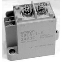
... DC Power Relays G9EA/G9EB/G9EC DC Control in a Relay A Leader in Clean Energy with Compact, Quiet, Energy-efficient Designs G9EB G9EA G9EC ...
Page 2
... OMRON has improved on the standard DC circuit that switches using a contactor or circuit-breaker by developing the G9EA/G9EB/G9EC DC Power Relay Series. These Relays enable switching high-voltage and high-capacity loads. The switch's gas-filled construction allows a considerable reduction in the relay switch size, while also lowering the operating noise during load switching ...
Page 3
... A at 400 VDC (100 times min.) − 200 VDC Reverse polarity inter- ruption (1,000 times min.) Coil Rated voltage 12, 24, 48, 60, and 100 VDC Power consumption Approx 5.4 W Mechanical endurance 200,000 operations min. G9EA G9EA-1(-B) G9EA-1(-B)-CA High-current conduction conduction 67 ...
Page 4
... Approx. 310 g Refer to page 5 Note: 1. The insulation resistance was measured with a 500-VDC megohmmeter. 2. The impulse withstand voltage was measured with a JEC-212 (1981) standard impulse voltage waveform (1.2 × 50 µ s). Selection Guide 4 DC Power Relays G9EA G9EA-1(-B) G9EA-1(-B)-CA High-current conduction conduction ) 67 ...
Page 5
... Two M3.5 screws are provided for the coil terminal connection. Terminals Contact form Contact terminals Screw terminals SPST-NO (See note 1.) DC Power Relays (60-A, 100-A Models) Rated coil voltage Model 12 VDC G9EA-1-B 24 VDC G9EA-1 48 VDC G9EA-1-B-CA 60 VDC 100 VDC G9EA-1-CA G9EA-1 5 ...
Page 6
... Approx age (at 23°C within 10 minutes) Approx. 5.2 W Approx. 5.4 W G9EA-1(-B)- Ω max. (0.3 m Ω typical) 0.1 V max. (for a carry current of 100 A) 400 VDC 1,000 ops. min. 120 VDC 2,500 ops. min. --- 150 A (10 min) --- 100 A at 120 VDC (150 times min ...
Page 7
... Engineering Data ■ G9EA-1(-B) Switching/Current Conduction Models Maximum Switching Capacity 1,000 500 300 G9EA-1 DC resistive load 100 100 300 500 1,000 Switching voltage (V) Carry Current vs Energizing Time 100,000 10,000 1,000 100 100 300 500 1,000 Carry current (A) ■ G9EA-1(-B)-CA High-current Conduction Models ...
Page 8
... All G9EA-1 Models Must-operate Voltage and Must-release Voltage Distributions 30 Must-operate voltage Sample: G9EA-1 Number: 35 Must-release voltage 100 Percentage of rated voltage (%) Vibration Resistance 10.0 Sample: G9EA-1 Number: 5 8.0 6.0 4.0 2.0 Must-release voltage 0.0 Must-operate voltage −2.0 −4.0 −6.0 −8.0 −10.0 ...
Page 9
... Terminal Arrangement/ Internal Connections (TOP VIEW) 1 (+) (−) 7 Note: Be sure to connect terminals with the correct polarity. Coils do not have polarity. Mounting Hole Dimensions (TOP VIEW) Two 6.5-dia. holes 67.2 60.7 (Terminal height) 10.5 24± 0.1 G9EA-1 8 61± 0.1 8 61± 0.1 9 ...
Page 10
... Dimensions of cutouts for wiring. Two, M5 61± 88 0.1 24± 0 G9EA-1 Note: Be sure to remove the cutouts for wiring that are located in 36 the wiring outlet direction be- fore installing the Terminal Cover. Dimension (mm) Tolerance (mm) ±0 lower ±0 ± higher Dimension (mm) Tolerance (mm) ± ...
Page 11
... DC Power Relays (200-A Models) G9EC-1 DC Power Relays Capable of Interrupting High-voltage, High-current Loads • A compact relay ( 86 H)) capable of switching 400-V 200-A DC loads. (Capable of interrupting 1,000 A at 400 VDC max.) • The switching section and driving section are gas-injected and hermetically sealed, allowing these compact relays to interrupt high-capacity loads ...
Page 12
... The impulse withstand voltage was measured with a JEC-212 (1981) standard impulse voltage waveform (1.2 × 50 µ s). 5. The mechanical endurance was measured at a switching frequency of 3,600 operations/hr. 6. The electrical endurance was measured at a switching frequency of 60 operations/hr Power Relays (200-A Models) Must-operate Must-release voltage 75% max ...
Page 13
... Switching current (A) Must-operate Voltage and Must-release Voltage Distributions 30 Must-operate voltage Sample: G9EC-1 Number: 35 Must-release voltage Percentage of rated voltage (%) DC Power Relays (200-A Models) Electrical Endurance (Interruption Performance) 1,000 500 300 Interrupting 400-VDC 100 resistive load (positive direction 100 500 1,000 10,000 Switching current (A) ...
Page 14
... Z' X' 600 800 Energized 1,000 Y' The value at which malfunction occurred was measured after applying shock to the test piece 3 times each in 6 directions along 3 axes Power Relays (200-A Models) Vibration Resistance 5.0 Sample: G9EC-1 Number: 5 4.0 3.0 2.0 1.0 Must-release voltage 0.0 Must-operate voltage − ...
Page 15
... G9EC-1 8 12VDC CONTACT: 200A 400VDC MADE IN JAPAN Lot No. 1362K1-0001 DC Power Relays (200-A Models) Terminal Arrangement/ Internal Connections (TOP VIEW) 1(+) 32 44 2(−) 7 Note: Be sure to connect terminals with the correct polarity. Coils do not have polarity. Mounting Hole Dimensions (TOP VIEW) Two ...
Page 16
... Options Terminal Cover P9EC Power Relays (200-A Models) 44 Dimensions of cutout for wiring G9EC-1 Note: Be sure to remove the cutouts for wiring that are located in the wiring outlet direction before in- stalling the Terminal Cover. Dimension (mm) Tolerance (mm) ±0 lower ±0 ± higher ...
Page 17
... Smallest and lightest in its class at 25 × 60 × and approx- imately 135 g. This is approximately half the volume and a third of the weight of other DC Power Relays in the same class (400 VDC, 25 A).* • The unique design of the contact switching component and per- manent magnet for blowing out the arc eliminates the need for polarity in the main circuit (contact terminal) ...
Page 18
... The electrical endurance was measured at a switching frequency of 60 operations/hr. 7. These values are for when a varistor is used as the protective circuit against reverse surge in the relay coil. Using a diode will reduce the switching characteristics Power Relays (25-A Models) Must-operate Must-release voltage 75% max. of rated 10% min ...
Page 19
... Must-operate Voltage and Must-release Voltage Distributions 30 Sample: G9EB-1-B Must-operate voltage 12 VDC Must-release voltage Number Percentage of rated voltage (%) DC Power Relays (25-A Models) Electrical Endurance (Interruption Performance) 1,000 500 300 100 Interrupting 250-VDC resistive load 100 300 500 1,000 Switching current (A) Time Characteristic ...
Page 20
... X' 150 Deenergized 200 Energized Y' The value at which malfunction occurred was measured after applying shock to the test piece 3 times each in 6 directions along 3 axes Power Relays (25-A Models) Vibration Resistance 5.0 Sample: G9EB-1-B 12 VDC Number: 5 4.0 3.0 2.0 1.0 Must-release voltage 0.0 Must-operate voltage − ...
Page 21
... Two, M4 49.2 (Coil M4 screw (Coil M4 screw dimensions) Two, M4 dimensions G9EB-1-B 12VDC CONTACT: 25A 250VDC MADE IN JAPAN 58 Lot No. 0424Y1-0001 18 Power Relays (25-A Models) Terminal Arrangement/ Internal Connections (TOP VIEW Mounting Hole Dimensions (TOP VIEW) Two 4.8-dia. holes 50± 0.1 13± 0.1 G9EB-1 21 ...
Page 22
... M5 screws: 1.57 to 2.35 N·m • M4 screws: 0.98 to 1.37 N·m • M3.5 screws: 0.75 to 1.18 N·m 2. The G9EA and G9EC Relays’ contacts have polarity. Be sure to perform connections with the correct polarity. If the contacts are connected with the reverse polarity, the switching characteristics specified in this document cannot be assured ...
Page 23
... Common Precautions DC Power Relay 23 ...
Page 24
... To convert millimeters into inches, multiply by 0.03937. To convert grams into ounces, multiply by 0.03527. Cat. No. J144-E1-03 In the interest of product improvement, specifications are subject to change without notice. OMRON RELAY & DEVICES Corporation DC Power Business Promotion Department 1110, Sugi, Yamaga-city, Kumamoto-Pref., 861-0596 Japan Tel: (81)968-44-4641/Fax: (81)968-44-4107 Printed in Japan 0606-0 ...