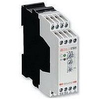
MK 7850N.82/200 AC/DC12-240V DOLD & SOEHNE, MK 7850N.82/200 AC/DC12-240V Datasheet - Page 3

MK 7850N.82/200 AC/DC12-240V
Manufacturer Part Number
MK 7850N.82/200 AC/DC12-240V
Description
RELAY, MULTIFUNCTION
Manufacturer
DOLD & SOEHNE
Specifications of MK 7850N.82/200 AC/DC12-240V
Contact Configuration
2PCO
Nom Input Voltage
240V
Delay Time Range
0.02s To 300h
Adjustment Type
Screwdriver Slot
Relay Mounting
DIN Rail
Coil Voltage Vac Nom
240V
Coil Voltage Vdc Nom
12V
Contact Current
RoHS Compliant
Svhc
No SVHC (15-Dec-2010)
Rohs Compliant
Yes
MK 7850N.82/200
Control of A1-A2 with proximity sensors
The input can be controlled by DC 3 wire or AC/DC 2 wire proximity
sensors. For operating voltage > 24 V and usage of sensors without
built-in short circuit protection a protection resistor on A1 is
recommendend to reduce the inrush current. The dimension is as
follows:
R
The series resistor must not be selected higher than necessary.
Max. values are:
Operating voltage:
Series resistor R
Instantaneous contact
By external wire links the output function of the device can be altered
from 2 delayed contacts to 1 delayed and 1 instantaneous contact.
The instantaneous contact switches when the operating voltage is
connected. To terminals X1 and X2 no other voltage potentials must
be connected, as the unit might be damaged.
Adjustment assistance
The flashing period of the yellow LED is 1 s ± 4 % and can be used to
adjust the time. Especially on the lower end of scale and for long times
it is suitable as the multiplication factors between the different time
ranges are exact without tolerance.
Example:
The required time is 40 min. It has to be adjusted within range
3 ... 300 min.The time check takes too long as several timing cycles
would be necessary for a precise value. For faster adjustment the
setting is made to 0.03 ... 3 min. On this range the potentiometer should
be set to 0.4 min (= 24 sec.). With the right potentiometer setting the
LED must show 24 flashing cycles. After that the time range is switched
over
3 ... 300 min. and the setting is complete.
Time interruption / time adding with B1
With the functions AV, EW, IE and BI the time delay can be interrupted
by controlling input B1 (+) with control voltage. Removing the control
signal will continue the timing cycle (time addition).
MK 7850N.82/500
Circuit diagrams
v
Notes
≈ operating voltage / max. switching current of sensor
A1 B1 Z1
A2 Z2 Z3
A1 B1
A2
A1
26
22
16
A1
26
22
16
Z1 Z2 Z3
15
28
24
18
15
28
24
18
16 18
16 18
15
25
21
X1 X2
25
21
X1 X2
v
15
max: 270 Ω 390 Ω
(+)
Z3
(+)
Z1
B1
X3
A2
B1
X3
A2
26
22
26
22
25
21
48 V
28
24
25
21
M8100_a
M8101_a
28
24
t1
t2
Z2
60 V
MK 7850N.82/300
110 V
680 Ω
A1 B1 Z1
A2
Z2
A1
26
22
16
Z1 Z2
230 V
1,8 kΩ (1 W)
15
28
24
18
16 18
25
21
X1 X2
15
Z1
(+)
B1
X3
A2
26
22
25
21
28
24
t
M8676_a
Z2
to
Control input B1
The functions RV, IF, AW, AV / RV have to be controlled via input B1
(+) with voltage against A2. The control signal could be the same as
the auxiliary/control voltage of A1 or any other voltage between 12 and
240 V AC or DC. Operating a parallel load between B1 and A2 is also
possible.
If with function IF the inputs A1 and B1 are controlled simultaneously
a pulse with the adjusted length is started. With the variant MK7850N/
500 the output pulse can be disabled by setting the slide switch in
Position "B".
Time interruption and time addition with X3
On all functions, also with RV,IF, AW (EW/AW) and AB/RV the time
delay can be interrupted during timing by bridging the terminals
X2 - X3. By opening the bridge the time continues (time addition).
While X2 and X3 are bridged the control input is disabled and the yellow
LED remains in the state it had at stop. No external voltage must be
connected to X2 and X3 as the unit may be damaged.
Remote potentiometers
Both settings on variant MK 7850N/500 can also be made by remote
potentiometers of 10 kOhms:
- terminals Z1 - Z2: potentiometer for time t1
- terminals Z2 - Z3: potentiometer for time t2
When connecting a remote potentiometer the corresponding
potentiometer has to be set to min. If no remote potentiometers are
required the terminals Z1-Z2 resp. Z2-Z3 have to be linked.
The wires to the remote potentiometers should be installed separately
from the lines with mains voltage. If this is not possible, a screened
cable is recommendet where the shield is connected to Z2.
To terminals Z1, Z2 and Z3 no external voltage must be connected,
as the unit might be damaged.
Additional function
With the variant MK7850N/500 additional features can be selected for
the functions position 3, 4 and 7 using the slide switch S1 on the relay
front in position "B". At the same time a second time setting t2 is
available on the lower potentiometer (see function diagram) the time
range is the same as for t1.
3
slide switch S1
(only with MK7850N/500)
Setting
Notes
green LED
on when voltage
connected
yellow LED
function see
indicators
M8302_a
range selector switch
time setting t 1
function setting
time setting t 2
(only with MK7850N/500)


