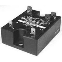
W6440ASX-1 Magnecraft / Schneider Electric, W6440ASX-1 Datasheet - Page 7

W6440ASX-1
Manufacturer Part Number
W6440ASX-1
Description
SSR, PANEL MOUNT, 480VAC, 280VAC, 40A
Manufacturer
Magnecraft / Schneider Electric
Datasheet
1.6210AXXSZS-AC90.pdf
(28 pages)
Specifications of W6440ASX-1
Control Voltage Range
90VAC To 280VAC
Operating Voltage Range
48VAC To 480VAC
Load Current
40A
Isolation Voltage
4000VAC
Control Voltage Type
AC
Relay Terminals
Screw
Lead Free Status / RoHS Status
Lead free / RoHS Compliant
SOLID STATE RELAYS
CAPACITIVE LOADS: Caution must be used with low
impedance capacitive loads to verify that the di/dt
capabilities are not exceeded. The di/dt of a discharged
capacitive load without external limiting impedance
can approach infinity. Zero voltage turn-on is a
particularly valuable means of limiting di/dt with
capacitive loads.
MOTORS: Motors frequently have severe inrush
currents during starting and can impose unusual
voltages during turnoff. The inrush currents
connected to mechanical loads having high starting
torque or inertia should be carefully determined to verify
that they are within the surge capabilities of the SSR.
A current shunt and oscilloscope should be used to
examine the duration of the inrush current. Motor
starting may frequently reoccur at short intervals and
the affect of repetitive inrush currents on the thermal
operating point of an SSR must be considered. Check
the motor operating current and locked rotor current
versus the SSR motor rating. The possibility of
abnormally stalled rotor conditions which draw much
higher than normal currents should be considered. An
extended stalled rotor condition may require an
oversized SSR or fuse protection. The generated EMF
of certain motors can require an SSR to have a blocking
voltage greater than might be expected from steady
state line voltage. The voltage applied to an SSR by
a motor circuit during turnoff should be examined with
an oscilloscope to verify hat the applied voltages are
safely below the specified SSR blocking voltages.
Otherwise lock-on or erratic turnoff of the motor may
occur. Some motor circuits may require higher than
normal blocking voltage, transient limiting devices, or
other techniques to control the voltage which must be
blocked by an SSR during deceleration or direction
reversal.
TRANSFORMERS:
In controlling transformers, the characteristics of the
secondary load should be considered because it reflects
the effective load on the SSR. Voltage transients from
secondary load circuits, similarly, are frequently
transformed and can be imposed on the SSR.
Transformers present a special problem in that,
depending on the state of the transformer flux at the
time of turnoff, the transformer may saturate during
the first half-cycle of subsequent applied voltage. This
saturation can impose a very large current (Commonly
ten to one hundred times rated primary current) on the
SSR and exceed its half-cycle surge rating.
SSR's having random turn-on may have a better chance
of survival than a zero voltage turn-on device for they
commonly require the transformer to support only a
APPLICA
APPLICA
portion of the first half-cycle of the voltage. On the
other hand, a random turn-on device will frequently
close at the essentially zero voltage point (start of the
half-cycle) and then the SSR must sustain the worst-
case saturation current. A zero voltage turn-on device
has the advantage that it turns on in a known, predictable
mode and will normally immediately demonstrate
(dependent on turnoff flux polarity) the worst-case
condition. The use of an oscilloscope is recommended
to verify that the half-cycle surge capability of the SSR
is not exceeded. The severity of the transformer
saturation problem varies greatly, dependent on the
magnetic material of the transformer, saturated primary
impedance, line impedance, etc.
A safe rule of thumb in applying an SSR to a transformer
primary is to select an SSR having a half-cycle current
surge rating (RMS) greater than the maximum applied
line voltage (RMS) divided by the transformer primary
resistance. The primary resistance is usually easily
measured and can be relied on as a minimum impedance
limiting the first half-cycle of inrush current. The
presence of some residual flux plus the saturated
reactance of the primary will then further limit, in the
worst case, the half-cycle surge safely within the surge
rating of the SSR.
SELECTING THE PROPER SSR
NOMINAL LOAD CURRENT: Initially select a relay whose
current rating exceeds the normal load current. Using
the load current vs, temperature charts for that relay,
check the actual current capacity at the ambient
temperature to which the relay will be subjected.
As an example, the chart shows that a 25 ampere relay
provided with a suitable heat sink can safely carry a
maximum of 22 amperes
continuously
at 40˚C ambient.
Since heat degrades
the components
ability to carry
current, every
effort should be
made to keep the
operating
temperature of
the SSR as low
as possible.
TION DA
TION DA
40
15
35
30
25
20
10
5
MAX. AMBIENT TEMPERATURE (˚C)
20
6" x 6" x 1/8"
Aluminum
Plate
Mounted on Heat Sink with
1˚C/W thermal resistance.
(Sink to Ambient)
25 Amp Styles
40
T
60
T
A
A
80
100
2
6


