AEDS-9641-210 Avago Technologies US Inc., AEDS-9641-210 Datasheet - Page 5
AEDS-9641-210
Manufacturer Part Number
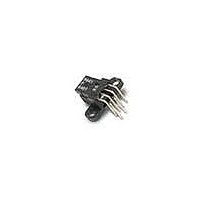
AEDS-9641-210
Description
ENCODER DGTL 2CH 300LPI BENT LD
Manufacturer
Avago Technologies US Inc.
Series
AEDS-964xr
Datasheet
1.AEDS-9641-210.pdf
(10 pages)
Specifications of AEDS-9641-210
Termination Style
Terminal Pins
Encoder Type
Optical
Output Type
Quadrature (Incremental)
Pulses Per Revolution
300 LPI
Voltage - Supply
3.3VDC
Actuator Type
Codestrip Not Included
Detent
No
Built In Switch
No
Mounting Type
Chassis Mount
Orientation
Right Angle
Number Of Channels
2
Mounting Style
PCB
Output
Quadrature
Supply Voltage
3.3 V, 5 V
Operating Temperature Range
0 C to + 70 C
Product
Optical
Technology
Linear and Rotary
Lead Free Status / RoHS Status
Lead free / RoHS Compliant
Rotational Life (cycles Min)
-
Lead Free Status / Rohs Status
Lead free / RoHS Compliant
Available stocks
Company
Part Number
Manufacturer
Quantity
Price
Company:

Part Number:
AEDS-9641-210
Manufacturer:
AVAGO
Quantity:
400
Part Number:
AEDS-9641-210
Manufacturer:
AVAGO/安华高
Quantity:
20 000


Electrical Characteristics
Electrical Characteristics over Recommend Operating Range, typical at 25°C
Encoding Characteristics
Encoding Characteristics over the Recommended
Operating Conditions and Mounting Conditions. These
characteristics do not include codewheel/codestrip
contribution.
1. The typical values are average over the full rotation
2. For a codestrip, the Typical Values are obtained at
Note: Refer to Figure 2 for output waveform on tr and tf
5
Parameter
Supply Current (Detector)
High Level Output Voltage
Low Level Output Voltage
Rise Time
Fall Time
LED Forward Voltage
Option P - 150 LPI
Option 1 & 2 - 300 & 360 LPI
Option P - 150 LPI
Option 1 & 2 - 300 & 360 LPI
of the codewheel at Nominal Mouting Position and
Typical Operating Conditions.
zero angular displacement and Typical Operating
Conditions.
I
Symbol Min.
V
V
t
tf
VF
CC
r
OH
OL
1.5
1.3
2.4
2.4
(turn on)
1.6
3.3V
3.0
3.3
3.3
200
50
Typ.@
3. Maximums are the worst case values predicted
Parameter
Pulse Width Error
Logic State Width Error
Phase Error
over the full range of Recommended Mounting
Tolerances and Operating Conditions, with
consideration to population shift.
1.8
Max.
8
5.2
5.2
0.4
0.4
Units
mA
ns
ns
V
V
V
V
V
Symbol Typ.
P
S
Notes
C
R
Typ. I
Typ. I
Typ. I
Typ. I
Typical I
L
L
= 11 kΩ
= 25 pF
OH
OH
OH
OH
7
5
2
= -0.7 mA @ 3.3 V
= -0.4 mA @ 3.3 V
= 8mA @ 3.3V
= 13mA @ 3.3V
F
= 16mA
Max. Units
40
40
20
e
e
e
Related parts for AEDS-9641-210
Image
Part Number
Description
Manufacturer
Datasheet
Request
R

Part Number:
Description:
Z10 Encoder,3Ch,500CPR
Manufacturer:
Avago Technologies US Inc.
Part Number:
Description:
Z10 En,3Ch,1000CPR,11.68mm Rop
Manufacturer:
Avago Technologies US Inc.
Part Number:
Description:
Z10 Encoder,3Ch,100CPR
Manufacturer:
Avago Technologies US Inc.
Part Number:
Description:
Z10 Encoder,3Ch,200CPR
Manufacturer:
Avago Technologies US Inc.
Part Number:
Description:
Z10 Encoder,3Ch,256CPR
Manufacturer:
Avago Technologies US Inc.
Part Number:
Description:
Z10 Encoder,3Ch,360CPR
Manufacturer:
Avago Technologies US Inc.
Part Number:
Description:
Z10 Encoder,3Ch,400CPR
Manufacturer:
Avago Technologies US Inc.
Part Number:
Description:
Z10 Encoder,3Ch,512CPR
Manufacturer:
Avago Technologies US Inc.

Part Number:
Description:
Z12, 6Ch-360CPR Encoder
Manufacturer:
Avago Technologies US Inc.
Datasheet:
Part Number:
Description:
Z12, 6Ch-720CPR Encoder
Manufacturer:
Avago Technologies US Inc.
Datasheet:

Part Number:
Description:
OPTOCOUPLER GATE DRV 2A 16-SOIC
Manufacturer:
Avago Technologies US Inc.
Datasheet:
Part Number:
Description:
OPTOCOUPLER 2CH 2.5A 16-SOIC
Manufacturer:
Avago Technologies US Inc.
Datasheet:

Part Number:
Description:
OPTOCOUPLER GATE DRV 0.4A 16SOIC
Manufacturer:
Avago Technologies US Inc.
Datasheet:

Part Number:
Description:
OPTOCOUPLER 2.0A 250KHZ 8-DIP
Manufacturer:
Avago Technologies US Inc.
Datasheet:

Part Number:
Description:
OPTOCOUPLER 2.0A 250KHZ GW 8-SMD
Manufacturer:
Avago Technologies US Inc.
Datasheet: