AEDA-3200-TB1 Avago Technologies US Inc., AEDA-3200-TB1 Datasheet - Page 4
AEDA-3200-TB1
Manufacturer Part Number
AEDA-3200-TB1
Description
IC ENCODER HI-RES 3CH 5000CPR
Manufacturer
Avago Technologies US Inc.
Series
AEDA-3200-Txxr
Type
Optical Encoderr
Datasheet
1.HEDS-8940.pdf
(7 pages)
Specifications of AEDA-3200-TB1
Pulses Per Revolution
5000
Termination Style
Terminal Pins
Encoder Type
Optical
Output Type
Quadrature with Index (Incremental)
Voltage - Supply
5VDC
Actuator Type
2mm Open Center
Detent
No
Built In Switch
No
Mounting Type
Chassis Mount, Motors
Orientation
Vertical
Number Of Channels
3
Mounting Style
PCB
Supply Voltage
5 V
Product
Optical
Technology
Rotary
Detents
No
Motion
Rotary
Index Output
Indexed
Encoder Signal
Digital
Shaft Diameter (mm)
2mm
Operating Supply Voltage (typ)
5VDC
Operating Temperature Min Deg. C
-40C
Operating Temperature Max Deg. C
125C
Terminal Type
PC Pins
Lead Free Status / RoHS Status
Lead free / RoHS Compliant
Rotational Life (cycles Min)
-
Lead Free Status / Rohs Status
Compliant


Definitions
Count (N): N refers to the cycles per revolution (CPR) of the
encoder output.
One Cycle (C): 360 electrical degrees (°e).
One Shaft Rotation: 360 mechanical degrees, N cycles (rotary
motion only).
Phase (φ): The number of electrical degrees between the
center of the high state on the channel A and the center of
the high state of channel B. This value is nominally 90°e.
Pulse Width (P): The number of the electrical degrees that an
output is a high-level during one cycle, nominally 180°e
or 1/2 a cycle.
Pulse Width Error (∆P): The deviation in electrical degrees of
the pulse width from its ideal value of 180°e.
Index Pulse Width (Po): The number of electrical degrees that
an index is high during one full shaft rotation. This value
is nominally 90°e or 1/4 cycle.
State Width (S): The number of the electrical degrees be-
tween a transition in the output of the channel B. There
are 4 states per cycle, each nominally 90°e.
State Width Error (∆S): The deviation in electrical degrees of
each state width from its ideal value of 90°e.
Recommended Operating Conditions
Parameter
Temperature
Supply Voltage
Frequency
Maximum Frequency and RPM
CPR
2500
5000
6000
7200
7500
Note:
1. Maximum frequency will be lower due to limitation in maximum RPM.
2. Maximum mechanical limit is 12000 RPM, operating limit is dependent on the maximum operating frequency.
Maximum Frequency (kHz)
750
750
750
750
750
1
Symbol
T
V
f
A
CC
Min.
-40
4.5
Typical
25
5.0
125
Maximum RPM
12000
9000
7500
6250
6000
Direction of Motor Rotation
When the codewheel rotates in a clockwise direction,
channel A will lead channel B (Figure 1 illustrates the defi-
nition of clockwise direction of codewheel rotation). When
the codewheel rotates in a counter-clockwise direction,
channel B will lead channel A.
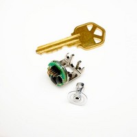
Figure 1. Viewed from the PCB encoder end.
Absolute Maximum Ratings
Storage Temperature
Operating Temperature
Supply Voltage
Output Voltage
Output Current per Channel
Frequency
Max.
125
5.5
750
2
Units
°C
Volts
kHz
Notes
Ripple <100 mVp-p
f = RPM x CPR
-40°C to 125°C
-40°C to 125°C
4.5 V to 5.5 V
-0.5 V to V
20 mA
750 kHz
60
cc
Related parts for AEDA-3200-TB1
Image
Part Number
Description
Manufacturer
Datasheet
Request
R

Part Number:
Description:
IC ENCODER HI-RES 3CH 2500CPR
Manufacturer:
Avago Technologies US Inc.
Datasheet:
Part Number:
Description:
IC ENCODER HI-RES 3CH 6000CPR
Manufacturer:
Avago Technologies US Inc.
Datasheet:
Part Number:
Description:
IC ENCODER HI-RES 3CH 7200CPR
Manufacturer:
Avago Technologies US Inc.
Datasheet:

Part Number:
Description:
IC ENCODER HI-RES 3CH 7500CPR
Manufacturer:
Avago Technologies US Inc.
Datasheet:

Part Number:
Description:
ENCODER KIT 3CH 2048CPR BOT MNT
Manufacturer:
Avago Technologies US Inc.
Datasheet:
Part Number:
Description:
ENCODER KIT 3CH 3000CPR BOT MNT
Manufacturer:
Avago Technologies US Inc.
Datasheet:

Part Number:
Description:
ENCODER KIT 3CH 2000CPR TOP MNT
Manufacturer:
Avago Technologies US Inc.
Datasheet:
Part Number:
Description:
ENCODER KIT 3CH 2048CPR TOP MNT
Manufacturer:
Avago Technologies US Inc.
Datasheet:
Part Number:
Description:
ENCODER KIT 3CH 6000CPR BOT MNT
Manufacturer:
Avago Technologies US Inc.
Datasheet:
Part Number:
Description:
ENCODER KIT 3CH 7200CPR BOT MNT
Manufacturer:
Avago Technologies US Inc.
Datasheet:

Part Number:
Description:
OPTOCOUPLER GATE DRV 2A 16-SOIC
Manufacturer:
Avago Technologies US Inc.
Datasheet:
Part Number:
Description:
OPTOCOUPLER 2CH 2.5A 16-SOIC
Manufacturer:
Avago Technologies US Inc.
Datasheet:

Part Number:
Description:
OPTOCOUPLER GATE DRV 0.4A 16SOIC
Manufacturer:
Avago Technologies US Inc.
Datasheet:

Part Number:
Description:
OPTOCOUPLER 2.0A 250KHZ 8-DIP
Manufacturer:
Avago Technologies US Inc.
Datasheet:

Part Number:
Description:
OPTOCOUPLER 2.0A 250KHZ GW 8-SMD
Manufacturer:
Avago Technologies US Inc.
Datasheet: