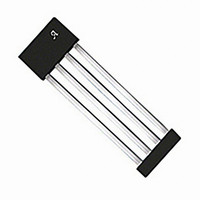
A1351LKTTN-T Allegro Microsystems Inc, A1351LKTTN-T Datasheet - Page 11

A1351LKTTN-T
Manufacturer Part Number
A1351LKTTN-T
Description
IC SENSOR HALL EFFECT 4-SIP
Manufacturer
Allegro Microsystems Inc
Type
Linear - Unipolar, Bipolarr
Datasheet
1.A1351LKTTN-T.pdf
(23 pages)
Specifications of A1351LKTTN-T
Sensing Range
0.055% ~ 0.095% DC/G
Voltage - Supply
4.5 V ~ 5.5 V
Current - Supply
10mA
Current - Output (max)
1mA
Output Type
Digital, Push-Pull
Features
High Precision
Operating Temperature
-40°C ~ 125°C
Package / Case
4-SIP
Lead Free Status / RoHS Status
Lead free / RoHS Compliant
Other names
620-1228-2
A1351
In customer applications the PWM interface circuitry (body con-
trol module; BCM in figure 12) and the A1351 may be powered
via different power and ground circuits. As a result, the ground
reference for the A1351 may differ from the ground reference of
the BCM. In some customer applications this ground difference
can be as large as ± 0.5 V. Differences in the ground reference for
the A1351 and the BCM can result in variations in the threshold
voltage used to measure the duty cycle of the A1351. If the PWM
conversion threshold voltage varies, then the duty cycle will
vary because there is a finite rise time (t
PWM waveform. This problem is shown in figure 13.
Figure 12. In many applications the A1351 may be powered using a different ground
reference than the BCM. This may cause the ground reference for the A1351 (GND 1)
to differ from the ground reference of the BCM (GND 2) by as much as to ± 0.5 V.
Figure 13. When the threshold voltage is correctly centered between V
the duty cycle accurately coincides with the applied magnetic field. If the threshold
voltage is raised, the output duty cycle appears shorter than expected. Conversely, if
the threshold voltage is lowered the output duty cycle is longer than expected.
with a Push/Pull, Pulse Width Modulated Output
r
) and fall time (t
High Precision Linear Hall Effect Sensor IC
A1351 Calibration Test Mode
f
) in the
The A1351 Output Calibration mode is used to compensate for
this error in the duty cycle. While the A1351 is in Output Calibra-
tion mode, the device output waveform is a fixed 50% duty cycle
(the programmed quiescent duty cycle value) regardless of the
applied external magnetic field. After powering-up, the 1351 out-
puts its quiescent duty cycle waveform for 800 ms, regardless of
the applied magnetic field (see figure 14). This allows the BCM
to compare the measured quiescent duty cycle with an ideal 50%
duty cycle.
This test period allows end users to compensate for any threshold
errors that result from a difference in system ground potentials.
OH
and V
115 Northeast Cutoff
1.508.853.5000; www.allegromicro.com
Allegro MicroSystems, Inc.
Worcester, Massachusetts 01615-0036 U.S.A.
OL
,
11


