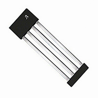
A1351LKTTN-T Allegro Microsystems Inc, A1351LKTTN-T Datasheet - Page 5

A1351LKTTN-T
Manufacturer Part Number
A1351LKTTN-T
Description
IC SENSOR HALL EFFECT 4-SIP
Manufacturer
Allegro Microsystems Inc
Type
Linear - Unipolar, Bipolarr
Datasheet
1.A1351LKTTN-T.pdf
(23 pages)
Specifications of A1351LKTTN-T
Sensing Range
0.055% ~ 0.095% DC/G
Voltage - Supply
4.5 V ~ 5.5 V
Current - Supply
10mA
Current - Output (max)
1mA
Output Type
Digital, Push-Pull
Features
High Precision
Operating Temperature
-40°C ~ 125°C
Package / Case
4-SIP
Lead Free Status / RoHS Status
Lead free / RoHS Compliant
Other names
620-1228-2
A1351
OPERATING CHARACTERISTICS (continued) valid over full operating temperature range, T
1
2
3
4
5
6
7
D
product.
8
9
specified value of Step
10
11
to and including Sens(max). See Characteristic Definitions section. Sensitivity may drift by an additional ±2.5% over the lifetime of this product.
12
13
14
15
unidirectional devices. These linearity ranges are only valid within the operating output range of the device. The operating output range is confined to the region between the
output clamps. Linearity may shift by up to ±0.25% over the lifetime of this product.
16
Drift Characteristics
Maximum Sensitivity Drift Through
Temperature Range
Sensitivity Drift Due to Package Hysteresis
Error Components
Linearity Sensitivity Error
Symmetry Sensitivity Error
See Characteristic Definitions section.
f
Measured as 10% to 90% (or 90% to 10%) of the PWM signal.
Jitter is dependent on the sensitivity of the device.
Raw device characteristic values before any programming.
Bit for selecting between D
D
Step size is larger than required, in order to provide for manufacturing spread. See Characteristic Definitions section.
Non-ideal behavior in the programming DAC can cause the step size at each significant bit rollover code to be greater than twice the maximum
(Q)
C
Overall programming value accuracy. See Characteristic Definitions section.
Sens(max) is the value available with all programming fuses blown (maximum programming code set). Sens range is the total range from Sens
Programmed at 125°C and calculated relative to 25°C.
PWM Carrier Frequency may drift by an additional ±17 Hz over the lifetime of this product.
Sensitivity drift from expected value at T
Symmetry error is only valid for bipolar devices. Symmetry may shift by up to ±0.6% over the lifetime of this product.
Linearity is only guaranteed for output duty cycle ranges of ±40% D from the quiescent output for bidirectional devices and +40% D from the quiescent output for
(Q)
varies up to approximately ±20% over the full operating ambient temperature range, T
(init) up to and including D
(max) is the value available with all programming fuses blown (maximum programming code set). The D
Characteristic
D(Q)
14
, Step
(Q)UNI
15
(Q)
16
SENS
(max). See Characteristic Definitions section. Quiescent Duty Cycle may drift by an additional –0.8% D to 0.3% D over the lifetime of this
and D
, or Step
(Q)BI
A
after programming TC
programming ranges.
fPWM
with a Push/Pull, Pulse Width Modulated Output
1
.
High Precision Linear Hall Effect Sensor IC
∆Sens
Symbol
∆Sens
Sym
Lin
ERR
ERR
PKG
SENS
TC
. See Characteristic Definitions section.
T
B = 400 G and 200 G, and
B = – 400 G and – 200 G
B = ±300 G
A
= 25°C, after temperature cycling
A
Test Conditions
, and process.
A
; C
(Q)
BYPASS
range is the total range from
= 0.1 μF, V
115 Northeast Cutoff
1.508.853.5000; www.allegromicro.com
Allegro MicroSystems, Inc.
Worcester, Massachusetts 01615-0036 U.S.A.
Min.
CC
–
–
–
–
= 5 V, unless otherwise specifi ed
< ±0.5
Typ.
< ±2
< ±1
< ±1
init
up
Max.
–
–
–
–
Units
%
%
%
%
5


