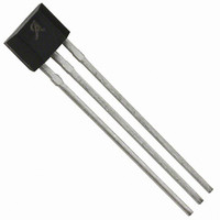
A1210LUA-T Allegro Microsystems Inc, A1210LUA-T Datasheet - Page 10

A1210LUA-T
Manufacturer Part Number
A1210LUA-T
Description
IC LATCH HALL EFFECT 3-SIP
Manufacturer
Allegro Microsystems Inc
Type
Bipolar Latchr
Datasheet
1.A1214LUA-T.pdf
(13 pages)
Specifications of A1210LUA-T
Sensing Range
150G Trip, -150G Release
Voltage - Supply
3.8 V ~ 24 V
Current - Supply
7.5mA
Current - Output (max)
25mA
Output Type
Digital, Open Drain
Operating Temperature
-40°C ~ 150°C
Package / Case
3-SIP
Operate Point Typ
150G
Termination Type
SIP
No. Of Pins
3
Hall Effect Type
Latching
Supply Voltage Min
3.8V
Operating Temperature Max
150°C
Peak Reflow Compatible (260 C)
Yes
Supply Voltage
24V
Output Current
25mA
Sensor Case Style
SIP
Supply Voltage Range
3.8V To 24V
Operating Temperature Range
-40°C To +150°C
Svhc
No SVHC (15-Dec-2010)
Rohs Compliant
Yes
Magnetic Type
Latch
Operating Supply Voltage (min)
3.8V
Operating Supply Voltage (typ)
5/9/12/15/18V
Operating Supply Voltage (max)
24V
Mag Sensor Operate Point (g)
150Gs
Mag Sensor Release Point (g)
-150Gs
Mag Sensor Hysteresis(g)
155Gs
Package Type
Ultra Mini SIP
Pin Count
3
Mounting
Through Hole
Operating Temp Range
-40C to 150C
Operating Temperature Classification
Automotive
Filter Terminals
SIP
Leaded Process Compatible
Yes
Operating Temperature Min
-40°C
Lead Free Status / RoHS Status
Lead free / RoHS Compliant
Features
-
Lead Free Status / Rohs Status
Compliant
Other names
620-1014
Available stocks
Company
Part Number
Manufacturer
Quantity
Price
Part Number:
A1210LUA-T
Manufacturer:
ALLEGRO/雅丽高
Quantity:
20 000
A1210, A1211,
A1212, A1213,
and
ADDITIONAL APPLICATIONS INFORMATION
Extensive applications information for Hall-effect devices is
available in:
• Hall-Effect IC Applications Guide, Application Note 27701
• Hall-Effect Devices: Gluing, Potting, Encapsulating, Lead
Welding and Lead Forming, Application Note 27703.1
• Soldering Methods for Allegro’s Products – SMT and Through-
Hole, Application Note 26009
All are provided in Allegro Electronic Data Book, AMS-702,
and the Allegro Web site, www.allegromicro.com.
Figure 2. Continuous-Time Application, B < B
Position 1, power is applied to the device. Position 2, the output assumes the correct state at a time prior to the maximum Power-On Time, t
The case shown is where the correct output state is HIGH . Position 3, t
valid, a control unit reads the output. Position 5, power is removed from the device.
A1214
V
V
OUT
CC
1
RP
.. This figure illustrates the use of a quick cycle for chopping V
2
t
PO(max)
PO(max)
3
has elapsed. The device output is valid. Position 4, after the output is
Continuous-Time Latch Family
Output Sampled
4
5
115 Northeast Cutoff
1.508.853.5000; www.allegromicro.com
Allegro MicroSystems, Inc.
Worcester, Massachusetts 01615-0036 U.S.A.
CC
in order to conserve battery power.
t
t
PO(max)
.
10


