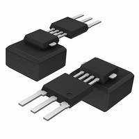
KMI16/1,115 NXP Semiconductors, KMI16/1,115 Datasheet - Page 3

KMI16/1,115
Manufacturer Part Number
KMI16/1,115
Description
SPEED SENSOR ROTATIONAL SOT477B
Manufacturer
NXP Semiconductors
Type
Special Purposer
Datasheet
1.KMI161115.pdf
(12 pages)
Specifications of KMI16/1,115
Sensing Range
2.9mm
Voltage - Supply
4.5 V ~ 16 V
Current - Supply
14mA
Current - Output (max)
20mA
Output Type
Digital, Open Collector
Features
Gear Tooth Type
Operating Temperature
-40°C ~ 150°C
Package / Case
SOT-477B
Lead Free Status / RoHS Status
Lead free / RoHS Compliant
Lead Free Status / RoHS Status
Lead free / RoHS Compliant, Lead free / RoHS Compliant
Other names
934055232115
KMI16/1 T/R
KMI16/1 T/R
KMI16/1 T/R
KMI16/1 T/R
Available stocks
Company
Part Number
Manufacturer
Quantity
Price
Company:
Part Number:
KMI16/1,115
Manufacturer:
NXP
Quantity:
1 200
Philips Semiconductors
LIMITING VALUES
In accordance with the Absolute Maximum Rating System (IEC 60134)
CHARACTERISTICS
T
9SMnPb28k; see Fig.6; centred sensor position; see notes 1, 2 and 3; unless otherwise specified.
Notes
1. High rotational wheel speeds reduce the maximum sensing distance because of eddy currents, depending on target
2. Output pins are designed for electrostatic sensitivity for more than 2000 V according to Human Body Model (HBM);
3. EMC behaviour depends greatly on design of application circuit.
2000 Sep 05
V
V
V
I
I
P
T
T
T
I
V
V
t
t
d
d
SYMBOL
SYMBOL
out(max)
out(off)
amb
CC
r
f
min
max
sld
stg
amb
CC
out
out(max)
tot
out (high)
CE sat
Integrated rotational speed sensor
wheel dimensions and materials used.
MIL-STD-883; method 3015.
= 25 C; V
DC operating supply voltage
voltage pin 1
OC output voltage
peak OC output voltage
OC output current
OC output leakage current
total power dissipation
soldering temperature
storage temperature
ambient operating temperature
supply current (pin 1)
OC output voltage high
OC saturation voltage
output signal rise time
output signal fall time
duty cycle
minimum sensing distance
maximum sensing distance T
CC
= 5 V; d = 1.9 mm; f
PARAMETER
PARAMETER
t
= 2 kHz; test circuit see Fig.5; gear wheel: module 2.08 mm; material
T
OC = off state; T
OC = on state; I
10% to 90%
10% to 90%
T
T
amb
amb
amb
amb
= 40 to +150 C
= 40 to +150 C
= 40 to +150 C
= 40 to +150 C
T
T
protection
T
protection; see Fig.5
T
protection; see Fig.5
T
T
T
t
amb
amb
amb
amb
amb
amb
amb
10 s
= 40 to +150 C
= 40 to +150 C; no wrong polarity
= 40 to +150 C; no wrong polarity
= 40 to +40 C; no wrong polarity
= 40 to +150 C
= 40 to +150 C
= 40 to +150 C
CONDITIONS
out
amb
3
= 20 mA
CONDITIONS
= 40 to +150 C 4.7
4
5
0.1
30
2.4
MIN.
4.5
10
4.9
0.4
12
0.4
50
0.3
2.9
0.5
0.5
0.5
65
40
MIN.
TYP.
Product specification
16
+16
+16
+26.5
20
100
200
260
+150
+150
14
1
20
10
70
0.5
MAX.
MAX.
KMI16/1
V
V
V
V
mA
mW
mA
V
V
%
mm
mm
C
C
C
UNIT
A
UNIT
s
s


