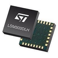
LSM303DLHTR STMicroelectronics, LSM303DLHTR Datasheet - Page 43

LSM303DLHTR
Manufacturer Part Number
LSM303DLHTR
Description
IC ACCELEROMETER 3AXIS 3D 28LGA
Manufacturer
STMicroelectronics
Datasheet
1.STEVAL-MKI063V1.pdf
(47 pages)
Specifications of LSM303DLHTR
Output Type
Digital - I²C
Sensor Type
Accelerometer and Magnetometer
Sensing Axis
Triple
Acceleration
2 g, 4 g, 8 g
Sensitivity
1 mg/digit, 2 mg/digit, 3.9 mg/digit
Package / Case
LGA-28L
Digital Output - Number Of Bits
16 bit
Supply Voltage (max)
3.3 V
Supply Voltage (min)
2.5 V
Maximum Operating Temperature
+ 85 C
Minimum Operating Temperature
- 30 C
Digital Output - Bus Interface
I2C
For Use With
497-10689 - BOARD ADAPTER LSM303DLH DIL24
Lead Free Status / RoHS Status
Lead free / RoHS Compliant
Other names
497-10765-2
LSM303DLHTR
LSM303DLHTR
Available stocks
Company
Part Number
Manufacturer
Quantity
Price
Company:
Part Number:
LSM303DLHTR
Manufacturer:
ST
Quantity:
8 295
Company:
Part Number:
LSM303DLHTR-SMJ
Manufacturer:
ST
Quantity:
8 305
LSM303DLH
9.2.8
impacts DRDY and RDY, which cannot be cleared until new data is placed in all the output
registers.
Status register
The status register (SR) is an 8-bit read-only register. This register is used to indicate device
status. SR0 through SR7 indicate bit locations, with SR denoting the bits that are in the
status register. SR7 denotes the first bit of the data stream.
Table 72.
Table 73.
IR_REG_M (0Ah/0Bh/0Ch)
The identification registers (IR) are used to identify the device. IR0 through IR7 indicate bit
locations, with IRA/IRB/IRC denoting the bits that are in the identification registers A, B & C.
IRA7/IRB7/IRC7 denotes the first bit of the data stream.
The identification value for this device is stored in this register. This is a read-only register.
Register values. ASCII value H
Table 74.
Table 75.
SR7 to SR3
MD1
SR2
SR1
SR0
0
0
0
Status register bit designations
SR register
IRA_REG_M
IRB_REG_M
LOCK
MD0
REN
RDY
0
1
0
0
These bits must be cleared for correct operation
Regulator enabled bit. This bit is set when the internal voltage regulator is
enabled. This bit is cleared when the internal regulator is disabled.
Data output register lock. This bit is set when some, but not all, of the six
data output registers have been read. When this bit is set, the six data
output registers are locked and any new data is not placed in these
registers until one of four conditions are met: one, all six have been read or
the mode changed, two, a POR is issued, three, the mode is changed, or
four, the measurement is changed.
Ready bit. Set when data is written to all six data registers. Cleared when
the device initiates a write to the data output registers, when in off mode,
and after one or more of the data output registers are written to. When RDY
bit is clear, it shall remain cleared for a minimum of 5 µs. The DRDY pin can
be used as an alternative to the status register for monitoring the device for
conversion data.
0
0
1
Doc ID 16941 Rev 1
0
0
1
0
1
0
Mode
REN
0
1
Registers description
LOC
0
0
RDY
0
0
43/47


