DS1822 Maxim Integrated Products, DS1822 Datasheet - Page 2
DS1822
Manufacturer Part Number
DS1822
Description
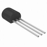
IC THERMOMETER ECONO DIG TO-92
Manufacturer
Maxim Integrated Products
Datasheet
1.DS1822Z.pdf
(21 pages)
Specifications of DS1822
Sensing Temperature
-55°C ~ 125°C
Output Type
Digital
Voltage - Supply
3 V ~ 5 V
Accuracy
±2°C
Package / Case
TO-226-3, TO-92-3 (TO-226AA)
Full Temp Accuracy
+/- 3 C
Digital Output - Bus Interface
Serial (1-Wire)
Digital Output - Number Of Bits
12 bit
Maximum Operating Temperature
+ 125 C
Minimum Operating Temperature
- 55 C
Lead Free Status / RoHS Status
Contains lead / RoHS non-compliant
Available stocks
Company
Part Number
Manufacturer
Quantity
Price

Part Number:
DS1822
Manufacturer:
DALLAS
Quantity:
20 000
Company:
Part Number:
DS1822+
Manufacturer:
MAXIM
Quantity:
3 400
Part Number:
DS1822Z
Manufacturer:
MAXIM/美信
Quantity:
20 000
Part Number:
DS1822Z+
Manufacturer:
MAXIM/美信
Quantity:
20 000
Part Number:
DS1822Z+T
Manufacturer:
MAXIM/美信
Quantity:
20 000
Company:
Part Number:
DS1822Z+T&R
Manufacturer:
MAXIM
Quantity:
3
Company:
Part Number:
DS1822Z+T/R
Manufacturer:
RENESAS
Quantity:
1 450


ORDER INFORMATION
ORDERING
NUMBER
DS1822
DS1822/T&R
DS1822+
DS1822+T&R
DS1822Z
DS1822Z/T&R
DS1822Z+
DS1822Z+T&R
Note: A “+” symbol will also be marked on the package.
DETAILED PIN DESCRIPTIONS Table 1
*All pins not specified in this table are “No Connect” pins.
OVERVIEW
Figure 1 shows a block diagram of the DS1822, and pin descriptions are given in Table 1. The 64-bit
ROM stores the device’s unique serial code. The scratchpad memory contains the 2-byte temperature
register that stores the digital output from the temperature sensor. In addition, the scratchpad provides
access to the 1-byte upper and lower alarm trigger registers (T
register. The configuration register allows the user to set the resolution of the temperature-to-digital
conversion to 9, 10, 11, or 12 bits. The T
retain data when the device is powered down.
The DS1822 uses Dallas’ exclusive 1-Wire bus protocol that implements bus communication using one
control signal. The control line requires a weak pullup resistor since all devices are linked to the bus via a
3-state or open-drain port (the DQ pin in the case of the DS1822). In this bus system, the microprocessor
(the master device) identifies and addresses devices on the bus using each device’s unique 64-bit code.
Because each device has a unique code, the number of devices that can be addressed on one bus is
virtually unlimited. The 1-Wire bus protocol, including detailed explanations of the commands and “time
slots,” is covered in the 1-WIRE BUS SYSTEM section of this data sheet.
Another feature of the DS1822 is the ability to operate without an external power supply. Power is instead
supplied through the 1-Wire pullup resistor via the DQ pin when the bus is high. The high bus signal also
charges an internal capacitor (C
method of deriving power from the 1-Wire bus is referred to as “parasite power.” As an alternative, the
DS1822 may also be powered by an external supply on V
8-PIN SO*
5
4
3
TO-92 SYMBOL DESCRIPTION
1
2
3
PACKAGE
MARKING
1822
1822
1822 (See Note)
1822 (See Note)
DS1822
DS1822
DS1822 (See Note)
DS1822 (See Note)
GND
V
DQ
DD
PP
), which then supplies power to the device when the bus is low. This
Ground.
Data Input/Output pin. Open-drain 1-Wire interface pin. Also
provides power to the device when used in parasite power mode
(see “Parasite Power” section).
Optional V
parasite power mode.
H
, T
L
and configuration registers are NV (EEPROM), so they will
DESCRIPTION
DS1822 in 3-pin TO92
DS1822 in 3-pin TO92, 2000 Piece Tape-and-Reel
DS1822 in Lead-Free 3-pin TO92
DS1822 in Lead-Free 3-pin TO92, 2000 Piece Tape-and-
Reel
DS1822 in 150 mil 8-pin SO
DS1822 in 150 mil 8-pin SO, 2500 Piece Tape-and-Reel
DS1822 in Lead-Free 150 mil 8-pin SO
DS1822 in Lead-Free 150 mil 8-pin SO, 2500 Piece
Tape-and-Reel
2 of 21
DD
pin. V
DD
.
DD
must be grounded for operation in
H
and T
L
), and the 1-byte configuration
DS1822
Related parts for DS1822
Image
Part Number
Description
Manufacturer
Datasheet
Request
R

Part Number:
Description:
MAX7528KCWPMaxim Integrated Products [CMOS Dual 8-Bit Buffered Multiplying DACs]
Manufacturer:
Maxim Integrated Products
Datasheet:
Part Number:
Description:
Single +5V, fully integrated, 1.25Gbps laser diode driver.
Manufacturer:
Maxim Integrated Products
Datasheet:
Part Number:
Description:
Single +5V, fully integrated, 155Mbps laser diode driver.
Manufacturer:
Maxim Integrated Products
Datasheet:
Part Number:
Description:
VRD11/VRD10, K8 Rev F 2/3/4-Phase PWM Controllers with Integrated Dual MOSFET Drivers
Manufacturer:
Maxim Integrated Products
Datasheet:
Part Number:
Description:
Highly Integrated Level 2 SMBus Battery Chargers
Manufacturer:
Maxim Integrated Products
Datasheet:
Part Number:
Description:
Current Monitor and Accumulator with Integrated Sense Resistor; ; Temperature Range: -40°C to +85°C
Manufacturer:
Maxim Integrated Products
Part Number:
Description:
TSSOP 14/A�/RS-485 Transceivers with Integrated 100O/120O Termination Resis
Manufacturer:
Maxim Integrated Products
Part Number:
Description:
TSSOP 14/A�/RS-485 Transceivers with Integrated 100O/120O Termination Resis
Manufacturer:
Maxim Integrated Products
Part Number:
Description:
QFN 16/A�/AC-DC and DC-DC Peak-Current-Mode Converters with Integrated Step
Manufacturer:
Maxim Integrated Products
Part Number:
Description:
TDFN/A/65V, 1A, 600KHZ, SYNCHRONOUS STEP-DOWN REGULATOR WITH INTEGRATED SWI
Manufacturer:
Maxim Integrated Products
Part Number:
Description:
Integrated Temperature Controller f
Manufacturer:
Maxim Integrated Products
Part Number:
Description:
SOT23-6/I�/45MHz to 650MHz, Integrated IF VCOs with Differential Output
Manufacturer:
Maxim Integrated Products
Part Number:
Description:
SOT23-6/I�/45MHz to 650MHz, Integrated IF VCOs with Differential Output
Manufacturer:
Maxim Integrated Products
Part Number:
Description:
EVALUATION KIT/2.4GHZ TO 2.5GHZ 802.11G/B RF TRANSCEIVER WITH INTEGRATED PA
Manufacturer:
Maxim Integrated Products
Part Number:
Description:
QFN/E/DUAL PCIE/SATA HIGH SPEED SWITCH WITH INTEGRATED BIAS RESISTOR
Manufacturer:
Maxim Integrated Products
Datasheet: