D2VW-5L1-1M Omron, D2VW-5L1-1M Datasheet - Page 2
D2VW-5L1-1M
Manufacturer Part Number
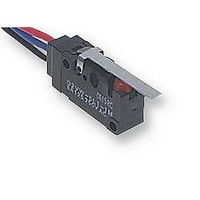
D2VW-5L1-1M
Description
MICROSWITCH, V3, LEVER
Manufacturer
Omron
Specifications of D2VW-5L1-1M
Contact Configuration
SPDT
Microswitch Type
Snap Action
Actuation Type
Lever
Contact Voltage Ac Nom
250V
Contact Voltage Dc Nom
30V
Contact Current Max
5A
Switch Terminals
Lead
Operating Force
1.18N
Actuator Style
Lever
Operating Force Max
1.18N
Rohs Compliant
Yes
Lead Free Status / RoHS Status
Lead free / RoHS Compliant


D2VW
Specifications
Note: The ratings values apply under the following test conditions:
Note: 1. The above current ratings are the values of the steady-state current.
Note: 1. The data given above are initial values.
D2VW-5
D2VW-01
D2VW-5
Operating speed
Operating frequency
Insulation resistance
Contact resistance (initial value)
Dielectric strength (see note 2)
Vibration resistance (see note 3)
Shock resistance (see note 3)
Durability (see note 4)
Degree of protection
Degree of protection against electric shock
Proof tracking index (PTI)
Ambient operating temperature (see note 5)
Ambient operating humidity
Weight
Ratings
Switching Capacity per Load (Reference Values)
Characteristics
Model
Model
Ambient temperature: 20±2°C
Ambient humidity: 65±5%
Operating frequency: 30 operations/min
2. Inductive load has a power factor of 0.7 min. (AC) and a time constant of 7 ms max. (DC).
3. Lamp load has an inrush current of 10 times the steady-state current.
2. The dielectric strength shown in the table indicates the value for models with a Separator.
3. For the pin plunger models, the above values apply for use at both the free position and total travel position. For the lever models,
4. For testing conditions, consult your OMRON sales representative.
5. The operating temperature of the lead wire (AV0.75f) for the molded lead wire model is between –40°C to 85°C.
they apply at the total travel position.
125 VAC
250 VAC
30 VDC
125 VDC
Voltage
250 VAC
125 VAC
30 VDC
125 VAC
30 VDC
Rated voltage
Item
5 A
5 A
5 A
0.4 A
NC
Resistive load
5 A
5 A
5 A
0.1 A
0.1 A
Resisteve load
Non-inductive load
0.1 mm to 1 m/s (pin plunger models)
Mechanical: 300 operations/min max.
Electrical:
100 MΩ min. (at 500 VDC)
50 mΩ max. (100 mΩ max. for molded lead wire models)
1,000 VAC, 50/60 Hz for 1 min between terminals of same polarity
1,500 VAC, 50/60 Hz for 1 min between current-carrying metal parts and ground
1,500 VAC, 50/60 Hz for 1 min between each terminal and non-current-carrying
metal parts
Malfunction: 10 to 55 Hz, 1.5-mm double amplitude
Destruction: 1,000 m/s
Malfunction: 300 m/s
Mechanical: 10,000,000 operations min. (60 operations/min)
Electrical:
IEC IP67 (excluding the terminals on terminal models)
Class I
175
–40°C to 85°C (at ambient humidity of 60% max.) (with no icing)
95% max. (for 5°C to 35_C)
Approx. 7 g (pin plunger models with terminals)
NO
0.5 A
0.5 A
3 A
0.1 A
30 operations/min max.
D2VW-5 models: 100,000 operations min. (30 operations/min)
D2VW-01 models: 1,000,000 operations min. (30 operations/min)
NC
Lamp load
2
{approx. 30G} max.
2
{approx. 100G} max.
NO
4 A
4 A
4 A
0.4 A
NC
Inductive load
Inductive load
NO
D2VW
215
Related parts for D2VW-5L1-1M
Image
Part Number
Description
Manufacturer
Datasheet
Request
R

Part Number:
Description:
SWITCH BASIC SPDT 5A W/WIRES
Manufacturer:
Omron
Datasheet:

Part Number:
Description:
SWITCH BASIC SPDT 5A .187QC
Manufacturer:
Omron
Datasheet:

Part Number:
Description:
MINIATURE BASIC SWITCH
Manufacturer:
Omron
Datasheet:

Part Number:
Description:
MINIATURE BASIC SWITCH
Manufacturer:
Omron
Datasheet:
Part Number:
Description:
MINIATURE BASIC SWITCH
Manufacturer:
Omron
Datasheet:
Part Number:
Description:
Miniature Basic Switch
Manufacturer:
Omron
Datasheet:
Part Number:
Description:
MINIATURE BASIC SWITCH
Manufacturer:
Omron
Datasheet:
Part Number:
Description:
MINIATURE BASIC SWITCH
Manufacturer:
Omron
Datasheet:
Part Number:
Description:
MINIATURE BASIC SWITCH
Manufacturer:
Omron
Datasheet:
Part Number:
Description:
MINIATURE BASIC SWITCH
Manufacturer:
Omron
Datasheet:

Part Number:
Description:
MINIATURE BASIC SWITCH
Manufacturer:
Omron
Datasheet:

Part Number:
Description:
MICRO SWITCH, SPDT-1NO/1NC, 5A, 250V
Manufacturer:
Omron
Datasheet:

Part Number:
Description:
MICRO SWITCH, SPDT-1NO/1NC, 5A, 250V
Manufacturer:
Omron
Datasheet:

Part Number:
Description:
MICRO SWITCH, SPDT-1NO/1NC, 5A, 250V
Manufacturer:
Omron
Datasheet:
Part Number:
Description:
MINIATURE BASIC SWITCH
Manufacturer:
Omron
Datasheet: