D2VW-5L1-1M Omron, D2VW-5L1-1M Datasheet - Page 6
D2VW-5L1-1M
Manufacturer Part Number
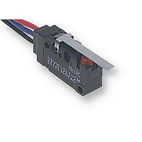
D2VW-5L1-1M
Description
MICROSWITCH, V3, LEVER
Manufacturer
Omron
Specifications of D2VW-5L1-1M
Contact Configuration
SPDT
Microswitch Type
Snap Action
Actuation Type
Lever
Contact Voltage Ac Nom
250V
Contact Voltage Dc Nom
30V
Contact Current Max
5A
Switch Terminals
Lead
Operating Force
1.18N
Actuator Style
Lever
Operating Force Max
1.18N
Rohs Compliant
Yes
Lead Free Status / RoHS Status
Lead free / RoHS Compliant


D2VW
Precautions
Refer to pages 26 to 31 for common precautions.
Degree of Protection
Do not use the Switch underwater. The Switch was tested and found
to meet the conditions necessary to meet the following standard.
The test checks for water intrusion after immersion for a specified
time period. The test does not check for switching operation under-
water.
IEC Publication 529, degree of protection IP67.
Protection Against Chemicals
Otherwise, damage to or deterioration of Switch materials may re-
sult.
Prevent the Switch from coming into contact with oil and chemicals.
Cat. No. C095-E1-03C
Cautions
ALL DIMENSIONS SHOWN ARE IN MILLIMETERS.
To convert millimeters into inches, multiply by 0.03937. To convert grams into ounces, multiply by 0.03527.
Mounting
Use M3 mounting screws with plane washers or spring washers to
securely mount the Switch. Tighten the screws to a torque of 0.39 to
0.59 N S m {4 to 6 kgf S cm}.
Operating Body
With the pin plunger models, set the Switch so that the plunger can
be pushed in from directly above. Since the plunger is covered with
a rubber cap, applying a force from lateral directions may cause
damage to the plunger or reduction in the sealing capability.
Handling
Handle the Switch carefully so as not to break the sealing rubber of
the plunger.
Using Micro Loads
Using a model for ordinary loads to open or close the contact of a
micro load circuit may result in faulty contact. Use models that oper-
ate in the following range. However, even when using micro load
models within the operating range shown below, if inrush current oc-
curs when the contact is opened or closed, it may increase contact
wear and so decrease durability. Therefore, insert a contact protec-
tion circuit where necessary.
The minimum applicable load is the N-level reference value. This
value indicates the malfunction reference level for the reliability lev-
el of 60% (λ 60). The equation, λ 60 = 0.5 10
cates that the estimated malfunction rate is less than 1/2,000,000
operations with a reliability level of 60%.
Correct Use
Inoperable
range
Incorrect
Correct
Operating range
for micro load
models D2VW-01
Incorrect
Current (mA)
Operating
range for
general-load
models
D2VW-05
–6
/operations indi-
D2VW
219
Related parts for D2VW-5L1-1M
Image
Part Number
Description
Manufacturer
Datasheet
Request
R

Part Number:
Description:
SWITCH BASIC SPDT 5A W/WIRES
Manufacturer:
Omron
Datasheet:

Part Number:
Description:
SWITCH BASIC SPDT 5A .187QC
Manufacturer:
Omron
Datasheet:

Part Number:
Description:
MINIATURE BASIC SWITCH
Manufacturer:
Omron
Datasheet:

Part Number:
Description:
MINIATURE BASIC SWITCH
Manufacturer:
Omron
Datasheet:
Part Number:
Description:
MINIATURE BASIC SWITCH
Manufacturer:
Omron
Datasheet:
Part Number:
Description:
Miniature Basic Switch
Manufacturer:
Omron
Datasheet:
Part Number:
Description:
MINIATURE BASIC SWITCH
Manufacturer:
Omron
Datasheet:
Part Number:
Description:
MINIATURE BASIC SWITCH
Manufacturer:
Omron
Datasheet:
Part Number:
Description:
MINIATURE BASIC SWITCH
Manufacturer:
Omron
Datasheet:
Part Number:
Description:
MINIATURE BASIC SWITCH
Manufacturer:
Omron
Datasheet:

Part Number:
Description:
MINIATURE BASIC SWITCH
Manufacturer:
Omron
Datasheet:

Part Number:
Description:
MICRO SWITCH, SPDT-1NO/1NC, 5A, 250V
Manufacturer:
Omron
Datasheet:

Part Number:
Description:
MICRO SWITCH, SPDT-1NO/1NC, 5A, 250V
Manufacturer:
Omron
Datasheet:

Part Number:
Description:
MICRO SWITCH, SPDT-1NO/1NC, 5A, 250V
Manufacturer:
Omron
Datasheet:
Part Number:
Description:
MINIATURE BASIC SWITCH
Manufacturer:
Omron
Datasheet: