D10INFP BANNER ENGINEERING, D10INFP Datasheet - Page 4
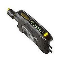
D10INFP
Manufacturer Part Number
D10INFP
Description
Photoelectric Sensor
Manufacturer
BANNER ENGINEERING
Type
Analog And Discrete Outputr
Datasheet
1.D10INFP.pdf
(16 pages)
Specifications of D10INFP
Sensor Output
NPN
Contact Current Max
150mA
Switch Terminals
Connector
Peak Reflow Compatible (260 C)
No
Sensor Input
Fiber Optic
Output Type
Transistor
Leaded Process Compatible
No
Fiber Optic Sensor Type
Analog And Discrete Output


Output 1 is configured for either 4 to 20 mA or 0 to 10V dc analog output, depending
on the model. The sensor may be programmed using the two-point TEACH (either
static or dynamic) or single-point static teach.
Teaching two setpoints (static or dynamic): The sensor sets the first taught condition
to the highest output level (either 20 mA or 10V), and the second taught condition
to the lowest level (either 4 mA or 0V), and scales between these points. If the first
condition taught has more returned light, the sensor will be in Light Operate
mode (LO). If the first taught condition is darker, the sensor will be in Dark Operate
mode (DO). To change the slope of the analog output (refer to Figure 2), toggle LO/DO
in Setup (page 9).
Single-point (static) Teach: The sensor sets the taught condition to the mid-point of its
range (12 mA or 5V, depending on the model). For Light Operate mode, the sensor will
automatically scale up to 20 mA (or 10V) for maximum light condition (the maximum
possible received signal) and down to 4 mA (or 0V) for maximum dark condition (no
signal), and vice-versa for Dark Operate mode. To change the slope of the analog
output (refer to Figure 3), toggle LO/DO in Setup (page 9).
An OFF-delay enabled for the analog output acts as an averaging function. During the
OFF-delay period, the sensor will take multiple analog readings and average the result
before changing the analog value. This acts to reduce the effects of major spikes in the
analog system, in effect “smoothing” the output reading.
NOTE: Depending on the application configuration and fibers used, the analog function
Figure 2. Analog output as a function of target position –
D10 Expert
4
Current-Sourcing
Models
P/N 65448 rev. E
20 mA
4 mA
may or may not behave linearly. The received light intensity will be dictated by
the inverse square properties of light.
two setpoints (static or dynamic)
Dark
™
Analog and Discrete Outputs
Signal
Slope
Slope
DO
LO
Analog Outputs
Light
Voltage-Sourcing
10V dc
0V dc
Models
Figure 3. Analog output as a function of target position –
Current-Sourcing
Models
20 mA
12 mA
4 mA
single-point TEACH
Max.
Dark
Banner Engineering Corp.
www.bannerengineering.com • Tel: 763.544.3164
Signal
Slope
Slope
Single Point
LO
DO
Taught
Max.
Light
•
Minneapolis, MN U.S.A.
Voltage-Sourcing
10V dc
5V dc
0V dc
Models
Related parts for D10INFP
Image
Part Number
Description
Manufacturer
Datasheet
Request
R

Part Number:
Description:
Photoelectric Sensor
Manufacturer:
BANNER ENGINEERING
Datasheet:

Part Number:
Description:
Photoelectric Sensor
Manufacturer:
BANNER ENGINEERING
Datasheet:

Part Number:
Description:
LEDIR70XD4-XM-81039 MAX INTENS STROBE ONLY NO BANNER MARKS
Manufacturer:
BANNER ENGINEERING
Part Number:
Description:
M18SP6DL-72225 LABELED MOELLER NO BANNER MARKINGS BULK PACK
Manufacturer:
BANNER ENGINEERING
Part Number:
Description:
M18SP6DLQ-72226 LABLED MOELLER NO BANNER MARKINGS BULK PACK
Manufacturer:
BANNER ENGINEERING
Part Number:
Description:
M18SP6L-72223 LABELED MOELLER NO BANNER MARKINGS BULK PACK
Manufacturer:
BANNER ENGINEERING
Part Number:
Description:
M18SP6LQ-72224 LABELED MOELLER NO BANNER MARKINGS BULK PACK
Manufacturer:
BANNER ENGINEERING
Part Number:
Description:
P4D1-77908 P4 DRIVER GENERIC NO BANNER MARKINGS RESALE TO CUSTOMER
Manufacturer:
BANNER ENGINEERING
Part Number:
Description:
Photoelectric Sensor
Manufacturer:
BANNER ENGINEERING
Datasheet:

Part Number:
Description:
Programmable Indicator Light
Manufacturer:
BANNER ENGINEERING
Datasheet:
Part Number:
Description:
INDICATOR LED PANEL 50MM GRN/RED/YEL 30V
Manufacturer:
BANNER ENGINEERING
Datasheet:
Part Number:
Description:
Programmable Indicator Light
Manufacturer:
BANNER ENGINEERING
Datasheet: