E3S-CD12 Omron, E3S-CD12 Datasheet - Page 9
E3S-CD12
Manufacturer Part Number
E3S-CD12
Description
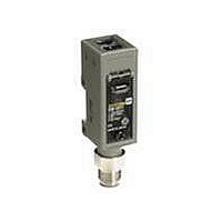
Photoelectric Sensor
Manufacturer
Omron
Type
Long Range Metal Body Sensorr
Series
E3S-Cr
Specifications of E3S-CD12
Output Current
100mA
Supply Voltage Range Dc
10V To 30V
Sensor Housing
Rectangular
Sensor Input
Optical
Sensing Range Max
2m
Switch Terminals
Wire Leaded
Features
Mutual interference protection
Height
29.5 mm
Length
50 mm
Maximum Operating Temperature
+ 55 C
Minimum Operating Temperature
- 25 C
Operating Supply Voltage
10 V to 30 V
Width
40.4 mm
Sensing Distance
2000 mm
Output Configuration
NPN or PNP
Sensing Method
Reflective, Diffuse
Sensing Object
White Paper
Sensing Light
Infrared
Mounting Type
Bracket Mount, Horizontal
Current - Supply
40mA
Voltage - Supply
10 V ~ 30 V
Package / Case
Module, Connector
Lead Free Status / RoHS Status
Lead free / RoHS Compliant
Lead Free Status / RoHS Status
Lead free / RoHS Compliant, Lead free / RoHS Compliant
Available stocks
Company
Part Number
Manufacturer
Quantity
Price
Company:

Part Number:
E3S-CD12
Manufacturer:
SANYO
Quantity:
20 520


Note: Models numbers for Through-beam Sensors (E3S-CT61(-M1J)) are for sets that include both the Emitter and Receiver.
Through-beam (Vertical)
E3S-CT61(-M1J)
Retro-/Diffuse-reflective (Horizontal)
E3S-CR11(-M1J)
E3S-CD11(-M1J)
E3S-CD12(-M1J)
23
The model number of the Emitter is expressed by adding "-L" to the set model number (example: E3S-CT61-L 2M), the model number of the Receiver, by adding "-D"
(example: E3S-CT61-D 2M.) Refer to Ordering Information to confirm model numbers for Emitter and Receivers.
Optical axis
Stability indicator (green)
23
9
A *
*1. The Mounting Bracket can be attached to side A.
*2. The Emitters for Through-beam Sensors only have the power indicator (red).
*3. The Emitter cable is 4-dia.vinyl-insulated round cable with 2 conductors (conductor cross section: 0.3 mm
A *
Lens (17 × 11)
1
insulator diameter: 1.3 mm) and a standard length of 2 m.
*The Mounting Bracket can be attached to side A.
M3 × 5
7.2
Emitter
Light indicator (red)*2
Receiver
Two, M4
5.8
Two, M4
20.2
1
Optical axis
1.5
9.3
22.2
18
4
2.2
With Mounting Bracket Attached
22.2
With Mounting Bracket Attached
Lens (17 × 11)
Stability indicator
(green)
2.2
15.8
9.2
Optical axis
23.2
18.5
4.2
20.8
7.4
6.2
12.9
Light indicator (red)
57
50
4.2
38.2
25.4
43.8
31
25.4
4.2
8.3
12.9
M3 × 5
2
,
Stainless steel
(SUS304)
4.2
4-dia. vinyl-insulated round cable
Standard length: 300 mm
Stainless steel
(SUS304)
4.2
1.5
4-dia. vinyl-insulated round cable
Standard length: 300 mm
4-dia. vinyl-insulated round cable with 3 conductors
(Conductor cross section: 0.2 mm
Insulator diameter: 1.2 mm),
Standard length: 2 m *3
17.3
20
4-dia. vinyl-insulated round cable with 3 conductors
(Conductor cross section: 0.2 mm
Insulator diameter: 1.2 mm),
Standard length: 2 m
9.2
20
12
20.4
29.5
20
20.4
32.2
20
Pre-wired Connector (-M1J)
Pre-wired Connector (-M1J)
2
(AWG24),
2
(AWG24),
Mounting Holes
Mounting Holes
Two, M4
M12 × 1
Two, M4
25.4
M12 × 1
25.4
E3S-C
9
Related parts for E3S-CD12
Image
Part Number
Description
Manufacturer
Datasheet
Request
R

Part Number:
Description:
SENSOR PHOTO HORZ 98' THRUBEAM
Manufacturer:
Omron
Datasheet:

Part Number:
Description:
SENSOR PHOTO VERT 98' THRUBEAM
Manufacturer:
Omron
Datasheet:

Part Number:
Description:
HOR, T-BEAM 30M CONN.
Manufacturer:
Omron
Datasheet:
Part Number:
Description:
VERTICAL, T-BEAM 30M CONN.
Manufacturer:
Omron
Datasheet:
Part Number:
Description:
Industrial Photoelectric Sensors DIFFUSE REFLECTIVE
Manufacturer:
Omron
Datasheet:

Part Number:
Description:
Industrial Photoelectric Sensors POLAR RETROREFLECTIV
Manufacturer:
Omron
Datasheet:
Part Number:
Description:
Photoelectric Sensor
Manufacturer:
Omron
Datasheet:
Part Number:
Description:
Photoelectric Sensors - Industrial DIFFUSE REFLECTIVE
Manufacturer:
Omron
Datasheet:

Part Number:
Description:
Photoelectric Sensors - Industrial PHOTOELECTRIC SENSOR NC/NR
Manufacturer:
Omron

Part Number:
Description:
Photoelectric Sensors - Industrial 2M DIFFUSE NPN/PNP VERT
Manufacturer:
Omron
Datasheet:


Part Number:
Description:
G6S-2GLow Signal Relay
Manufacturer:
Omron Corporation
Datasheet:
Part Number:
Description:
Compact, Low-cost, SSR Switching 5 to 20 A
Manufacturer:
Omron Corporation
Datasheet:
Part Number:
Description:
Manufacturer:
Omron Corporation
Datasheet: