E3S-AT61 Omron, E3S-AT61 Datasheet - Page 12
E3S-AT61
Manufacturer Part Number
E3S-AT61
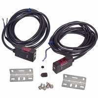
Description
Photoelectric Sensor
Manufacturer
Omron
Series
E3S-Ar
Type
Photoelectric Sensorr
Specifications of E3S-AT61
Output Current
100mA
Sensor Output
NPN
Supply Voltage Range Dc
10V To 30V
Sensor Housing
Rectangular
Output Type
Transistor
Sensor Input
Optical
Sensing Range Max
7m
Mounting Type
Bracket
Sensing Distance
275.591" (7m)
Sensing Method
Through-Beam
Output Configuration
NPN - Dark-ON/Light-ON - Selectable
Current - Supply
40mA
Voltage - Supply
10 V ~ 30 V
Response Time
0.5ms
Package / Case
Module, Pre-Wired
Features
Control the laser with digital fiber amplifier
Height
21 mm
Length
45.3 mm
Maximum Operating Temperature
+ 55 C
Minimum Operating Temperature
- 25 C
Operating Supply Voltage
10 V to 30 V
Width
12.4 mm
Lead Free Status / RoHS Status
Lead free / RoHS Compliant
Lead Free Status / RoHS Status
Lead free / RoHS Compliant, Contains lead / RoHS compliant by exemption
Other names
E3SAT61
OR586
OR586
Available stocks
Company
Part Number
Manufacturer
Quantity
Price
Company:

Part Number:
E3S-AT61
Manufacturer:
OMRON
Quantity:
384


Dimensions
E3S-A Built-in Amplifier Photoelectric Sensor
E3S-AT11/21/31/41 (Receiver)
A*
*The Mounting Bracket can be attached to side A.
Through-beam Sensors (Horizontal)
Pre-wired Sensors
A*
*The Mounting Bracket can be attached to side A.
E3S-AT21/41(Emitter)
Emitter: E3S-AT@@-L
Receiver: E3S-AT@@-D
E3S-AT11/31 (Emitter)
Optical axis
Optical axis
http://www.ia.omron.com/
1.2
1.2 10.7
10.7
28.9
5.5
28.9
5.5
28.9
29.2
With Mounting Bracket Attached
16.9
Optical
axis
29.2
Optical
axis
16.9
With Mounting Bracket Attached
Optical
axis
16.9
10.5
10.5
10.5
5
5
5
30
20
Unless otherwise specified, the tolerance class IT16 is used for dimensions in this data sheet.
30
20
20
30
Two, M3 × 12 screws
Two, M3 × 12 screws
7.2
7.2
7.2
Stainless steel
(SUS304)
Stainless steel
(SUS304)
3.1
3.1
3.1
7.2
7.2
7.2
21
Lens (7 × 7)
21
Lens (7 × 7)
8
8
(c)Copyright OMRON Corporation 2008 All Rights Reserved.
Power indicator (red)
12.4
Optical axis
12
Sensitivity adjuster (white)
Optical axis
*1. Not applicable to Sensors with timer adjusters (E3S-AT11 and E3S-AT31).
*2. The E3S-AT11 or E3S-AT31 has three conductors.
12.4
12.4
Light indicator
(red)
12.9
10.5
1.3
12
1.3
12
Stability indicator (green)
Mounting Holes
Two, M3 holes
12.9
10.5
12.5
10.5
40
20
20
17.8
Mounting Holes
Timer adjuster (black) *1
Two, M3 holes
Power indicator (red)
7
Turbo switch
40
20
40
20
20
5.5
(4)
Two, M3 × 12 screws
Two, M3 × 12 screws
4-dia. vinyl-insulated round
cable with 3 conductors
(Conductor cross section:
0.2 mm
Insulator diameter: 1.1 mm),
Standard length: 2 m
8.8 dia.
(4)
(4)
Operation mode
selector switch
2
,
4-dia. vinyl-insulated
round cable with
4 conductors
(Conductor cross
section: 0.2 mm
Insulator diameter:
1.1 mm),
Standard length: 2 m *2
4-dia. vinyl-insulated
round cable with
2 conductors
(Conductor cross
section: 0.2 mm
Insulator diameter:
1.1 mm),
Standard length: 2 m
8.8 dia.
E3S-A
8.8 dia.
(Unit: mm)
2
,
2
,
12
Related parts for E3S-AT61
Image
Part Number
Description
Manufacturer
Datasheet
Request
R

Part Number:
Description:
Sensor; Polarized Retroreflective Sensing Mode; Long Range Metal Body; 0 to 3 m
Manufacturer:
Omron Automation
Datasheet:
Part Number:
Description:
Sensor, Metal; NPN/PNP; Diffuse Mode Sensing Mode; Photoelectric; 27.56 in.
Manufacturer:
Omron Automation
Datasheet:
Part Number:
Description:
Sensor; NPN/PNP; Through-Beam Sensing Mode; Photoelectric; 30 m; 10 to 30 VDC
Manufacturer:
Omron Automation
Datasheet:
Part Number:
Description:
Sensor, Metal; NPN/PNP; Diffuse Mode Sensing Mode; Photoelectric; 27.56 in.
Manufacturer:
Omron Automation
Datasheet:

Part Number:
Description:
E3S-AT66 RECEIVER
Manufacturer:
Omron
Datasheet:

Part Number:
Description:
E3S-AT61 RECEIVER
Manufacturer:
Omron
Datasheet:
Part Number:
Description:
E3S-AT66 Emitter
Manufacturer:
Omron
Datasheet:
Part Number:
Description:
EMITTER ONLY FOR E3S-AT16
Manufacturer:
Omron
Datasheet:
Part Number:
Description:
RECEIVER ONLY FOR E3S-AT16
Manufacturer:
Omron
Datasheet:
Part Number:
Description:
RECEIVER ONLY FOR E3S-AT11
Manufacturer:
Omron
Datasheet:
Part Number:
Description:
G6S-2GLow Signal Relay
Manufacturer:
Omron Corporation
Datasheet:
Part Number:
Description:
Compact, Low-cost, SSR Switching 5 to 20 A
Manufacturer:
Omron Corporation
Datasheet:
Part Number:
Description:
Manufacturer:
Omron Corporation
Datasheet: