E2C-X1R5A Omron, E2C-X1R5A Datasheet - Page 14
E2C-X1R5A
Manufacturer Part Number
E2C-X1R5A
Description
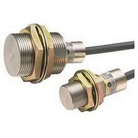
Inductive Proximity Sensor
Manufacturer
Omron
Series
E2Cr
Specifications of E2C-X1R5A
Sensor Input
Inductive
Sensing Range
3mm
Switch Terminals
Cable
Sensor Output
NPN, NO/NC
Peak Reflow Compatible (260 C)
No
Sensor Housing
Rectangular
Size
M8
Sensing Range Max
1.5mm
Proximity Sensor Sensing Distance
1.5mm
Proximity Sensor Sensing Distance Range
<2mm
Mounting
Panel
Operating Temp Range
-25C to 70C
Operating Temperature Classification
Commercial
Pin Count
2
Maximum Operating Temperature
+ 70 C
Sensing Distance
1.5 mm
Minimum Operating Temperature
- 25 C
Sensor Type
Inductive
Sensing Object
Metallic
Response Frequency
800Hz
Material - Body
Brass
Shielding
Shielded
Voltage - Supply
-
Output Type
-
Terminal Type
2-Wire
Package / Case
Cylinder, Threaded - M8
Lead Free Status / RoHS Status
Contains lead / RoHS non-compliant


* Cable Length Compensation Switching
Amplifier Unit Switch Settings
Note: 1. Mutual Interference Prevention: When mounting Sensors with the same diameter and cable length in parallel, set the DIP switch to modes that differ by 1 m
Applicable
Sensors
E2C-CR8A
E2C-CR8B
E2C-X1A
E2C-C1A
E2C-X1R5A
E2C-X2A
E2C-X5A
E2C-X10A
E2C-C20MA
Set this switch to the proper setting depending on whether the standard cable length is being used or the cable has been cut shorter.
Operation
switch
Changes NO/NC.
2. When using the E2C-CR5B + E2C-AM4A (or AK4A), set all the pins on the Amplifier Unit DIP switch to the left.
in cable length. Specifications, however, may not be sufficiently met, so always check operation before actual application. This method cannot be used for
the E2C-C20MA.
Cable length
compensation
switch*
Differential travel adjuster
length
Cable
0 to 1 m
A
B
C
D
A
B
C
D
1 to 2 m
A
B
C
D
A
B
C
D
2 to 3 m
The detection indicator (red)
indicates the detection status.
(Object detected: ON, No object
detected: OFF)
Stability indicator (green)
Indicates that the detection or
non-detection level is stable.
(Stable: ON, Unstable: OFF)
Sensing distance
adjustment
(4-turn potentiometer)
A
B
C
D
A
B
C
D
3 to 4 m
E2C-A@4A
A
B
C
D
A
B
C
D
4 to 5 m
A
B
C
D
A
B
C
D
Detection indicator (red)
Relay output
(transistor output)
5 to 6 m
Sensing object
Operation switch
——
A
B
C
D
6 to 7 m
Not present
——
ON
OFF
Present
OFF
Timing Chart
NO
ON
NC
A
B
C
D
7 to 8 m
——
A
B
C
D
E2C/E2C-H
8 to 9 m 9 to 10 m
——
A
B
C
D
——
A
B
C
D
14
Related parts for E2C-X1R5A
Image
Part Number
Description
Manufacturer
Datasheet
Request
R

Part Number:
Description:
M25, 4MM X 4M CABLE
Manufacturer:
Omron
Datasheet:
Part Number:
Description:
Proximity Sensors E2C-H15M SPECIAL
Manufacturer:
Omron
Datasheet:

Part Number:
Description:
Proximity Sensors SEP.AMP.PROX. M5 2m m DIST
Manufacturer:
Omron
Datasheet:
Part Number:
Description:
Proximity Sensors Prox Switch
Manufacturer:
Omron
Datasheet:

Part Number:
Description:
Proximity Sensors Smart Prox Sensor
Manufacturer:
Omron
Datasheet:

Part Number:
Description:
Proximity Sensors M25 4MMX1.5MCAB LEW/PLUG
Manufacturer:
Omron
Datasheet:
Part Number:
Description:
Proximity Sensors SEP.AMP.PROX 5.4MM 2mm DIST
Manufacturer:
Omron
Datasheet:
Part Number:
Description:
Proximity Sensors SEP.AMP.PROX. 2MM 1.2mm DIST
Manufacturer:
Omron
Datasheet:
Part Number:
Description:
Proximity Sensors E2C-C1A W/ 5 METER Cable
Manufacturer:
Omron
Datasheet:
Part Number:
Description:
Proximity Sensors SEP.AMP.PROX 3.MM 1.8mm DIST
Manufacturer:
Omron
Datasheet:

Part Number:
Description:
DC AMP NPN FOR E2C PROX
Manufacturer:
Omron
Datasheet:
Part Number:
Description:
DC AMP For M8 E2C-H HiTemp PRX
Manufacturer:
Omron
Datasheet:
Part Number:
Description:
DC AMP, M18 E2C-H HiTemp PROX
Manufacturer:
Omron
Datasheet:
Part Number:
Description:
SEP.AMP.PROX. M18, 10mm DIST
Manufacturer:
Omron
Datasheet: