E2C-X1R5A Omron, E2C-X1R5A Datasheet - Page 15
E2C-X1R5A
Manufacturer Part Number
E2C-X1R5A
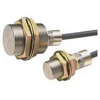
Description
Inductive Proximity Sensor
Manufacturer
Omron
Series
E2Cr
Specifications of E2C-X1R5A
Sensor Input
Inductive
Sensing Range
3mm
Switch Terminals
Cable
Sensor Output
NPN, NO/NC
Peak Reflow Compatible (260 C)
No
Sensor Housing
Rectangular
Size
M8
Sensing Range Max
1.5mm
Proximity Sensor Sensing Distance
1.5mm
Proximity Sensor Sensing Distance Range
<2mm
Mounting
Panel
Operating Temp Range
-25C to 70C
Operating Temperature Classification
Commercial
Pin Count
2
Maximum Operating Temperature
+ 70 C
Sensing Distance
1.5 mm
Minimum Operating Temperature
- 25 C
Sensor Type
Inductive
Sensing Object
Metallic
Response Frequency
800Hz
Material - Body
Brass
Shielding
Shielded
Voltage - Supply
-
Output Type
-
Terminal Type
2-Wire
Package / Case
Cylinder, Threaded - M8
Lead Free Status / RoHS Status
Contains lead / RoHS non-compliant


Safety Precautions
Refer to Warranty and Limitations of Liability.
This product is not designed or rated for ensuring
safety of persons either directly or indirectly.
Do not use it for such purposes.
Do not use the Encoder under ambient conditions that exceed the
ratings.
● Design
Influence of Surrounding Metal
When mounting the Sensor within a metal panel, ensure that the
clearances given in the following table are maintained. Failure to
maintain these distances may cause deterioration in the performance
of the Sensor.
Influence of Surrounding Metal
Note: Values in parentheses for diameter d are the outer diameters of Shielded
Mutual Interference
When installing Sensors face-to-face or side-by-side, ensure that the
minimum distances given in the following table are maintained.
Mutual interference can be prevented by using the cable length
compensation switch, but doing so will also change coil
characteristics. Specifications such as temperature specifications
and sensing distance, may not be sufficiently met, so always check
operation before actual application.
This method cannot be used for the E2C-G@4A, E2C-JC4A, E2C-
C20MA.
Mutual Interference
Note: The above values are for a differential travel setting of 5%.
Model
E2C-CR8
E2C-X1A
E2C-C1A
E2C-X1R5A(H)
E2C-X2A(H)
E2C-X5A(H)
E2C-X10A
E2C-C20MA
Model
E2C-CR8
E2C-X1A
E2C-C1A
E2C-X1R5A(H)
E2C-X2A(H)
E2C-X5A(H)
E2C-X10A
E2C-C20MA
Models.
Precautions for Correct Use
Distance
Distance
l
(Unit: mm)
A
m
25
100
300
0
20
30
50
l
A
WARNING
(3.5)
(5.4)
(12)
(18)
(30)
120
(5)
(8)
200
d
15
20
35
70
B
B
40
D
D
0
(Unit: mm)
d dia.
2.4
4.5
15
30
60
m
3
6
Mounting
Note: The above leeways in tighten torque assume that a toothed washer is
• Do not use excessive force when tightening the nuts on the E2C-X
E2C-X1A
E2C-X1R5A(H)
E2C-X2A(H)
E2C-X5A(H)
E2C-X10A
E2C-C20MA
• Mounting Unthreaded Cylindrical Models
and E2C-C20MA. A washer must be used with the nut.
When using a set screw, tighten it to a torque of 0.2 N·m max.
Dimpled end of
set screw (M3)
being used.
Model
7 to 11.5 mm
0.98 N·m
2.0 N·m
5.9 N·m
Torque
15 N·m
39 N·m
15 N·m
Y92E-F3R5 Mounting Bracket
(for 3.5 dia.) (Order Separately)
The Y92E-F5R4 (for 5.4 dia.)
is also sold separately.
E2C/E2C-H
15
Related parts for E2C-X1R5A
Image
Part Number
Description
Manufacturer
Datasheet
Request
R

Part Number:
Description:
M25, 4MM X 4M CABLE
Manufacturer:
Omron
Datasheet:
Part Number:
Description:
Proximity Sensors E2C-H15M SPECIAL
Manufacturer:
Omron
Datasheet:

Part Number:
Description:
Proximity Sensors SEP.AMP.PROX. M5 2m m DIST
Manufacturer:
Omron
Datasheet:
Part Number:
Description:
Proximity Sensors Prox Switch
Manufacturer:
Omron
Datasheet:

Part Number:
Description:
Proximity Sensors Smart Prox Sensor
Manufacturer:
Omron
Datasheet:

Part Number:
Description:
Proximity Sensors M25 4MMX1.5MCAB LEW/PLUG
Manufacturer:
Omron
Datasheet:
Part Number:
Description:
Proximity Sensors SEP.AMP.PROX 5.4MM 2mm DIST
Manufacturer:
Omron
Datasheet:
Part Number:
Description:
Proximity Sensors SEP.AMP.PROX. 2MM 1.2mm DIST
Manufacturer:
Omron
Datasheet:
Part Number:
Description:
Proximity Sensors E2C-C1A W/ 5 METER Cable
Manufacturer:
Omron
Datasheet:
Part Number:
Description:
Proximity Sensors SEP.AMP.PROX 3.MM 1.8mm DIST
Manufacturer:
Omron
Datasheet:

Part Number:
Description:
DC AMP NPN FOR E2C PROX
Manufacturer:
Omron
Datasheet:
Part Number:
Description:
DC AMP For M8 E2C-H HiTemp PRX
Manufacturer:
Omron
Datasheet:
Part Number:
Description:
DC AMP, M18 E2C-H HiTemp PROX
Manufacturer:
Omron
Datasheet:
Part Number:
Description:
SEP.AMP.PROX. M18, 10mm DIST
Manufacturer:
Omron
Datasheet: