C396A2A005SELXB EATON CUTLER HAMMER, C396A2A005SELXB Datasheet - Page 194
C396A2A005SELXB
Manufacturer Part Number
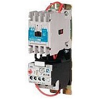
C396A2A005SELXB
Description
Electronic Overload Relay
Manufacturer
EATON CUTLER HAMMER
Datasheet
1.XTCE007B10A.pdf
(312 pages)
Specifications of C396A2A005SELXB
Overload Adjustment Current Min
1A
Overload Adjustment Current Max
5A
Frame Size
Standard
Contact Configuration
1NO / 1NC


34-194
34
Figure 34-147. Typical Wiring Diagram — Non-combination Starters (Reversing)
IEC Contactors & Starters
XT IEC Power Control
Contactors and Starters — Enclosed Control
Switch
SPDT
Electrically Interlocked
Rev
Pushbutton with FOR
For
Remote Control
and REV Buttons
Pushbutton
Stations
1
3
5
Stop
Stop
Rev
For
Rev
For
Pushbutton
Hold Down
For
Rev
4
1
5
1
2
3
5
3
2
4
3
1
5
L1 L2 L3
Front View of Panel
1
T1 T2 T3
Lines
Motor
AC
3
AC
Figure 1
OL
2
T1
5
T1
2
3 2
A1
F
4
T2
Lines to the Number 1 Terminal
on the Remote Pilot Device and
53
54
and Connect Separate Control
to the Number 96 Terminal on
For more information visit: www.eaton.com
T2
Remove Wire “C” if Supplied
4
61
62
A2
6
T3
the Overload Relay.
C320KGT5
T3
Separate Control
Auxiliary
6
Contact
96
Reset
95
98
97
Wire “F” – Used
with Local
Control
Pushbuttons
1
5 4
A1
R
53
54
“C”
61
62
A2
L1 L2 L3
1
Stop
Lines
Reversing Starter Elementary Diagram
Rev.
2
4
Contactors “F” and “R” are
Mechanically Interlocked
53
53
R
F
R
R
F
F
For.
F
R
54
54
5 62
3 62 61
R
F
OL
OL
OL
61
A1 F A2 OL
A1 R A2
“C”
T2
T1
T3
Motor
95
AC
CA08102001E
March 2009
96
Related parts for C396A2A005SELXB
Image
Part Number
Description
Manufacturer
Datasheet
Request
R

Part Number:
Description:
PROGRAMMABLE LOGIC CONTROLLER
Manufacturer:
EATON CUTLER HAMMER
Part Number:
Description:
Pm Power Pro 3000/5000 A-B Accel/On Interface
Manufacturer:
EATON CUTLER HAMMER
Part Number:
Description:
Handle Tie Bar For (2) - 1 Pole Type BR Breakers
Manufacturer:
EATON CUTLER HAMMER
Part Number:
Description:
Type CH Breaker 150A/2 Pole 120/240V 10K
Manufacturer:
EATON CUTLER HAMMER
Part Number:
Description:
Tenant Branch Breaker 125A/3 Pole 120/240V 42K
Manufacturer:
EATON CUTLER HAMMER
Part Number:
Description:
Type CL Breaker 25A/1Pole 120/240V 10K-Classified 1" Ckt Bkr
Manufacturer:
EATON CUTLER HAMMER
Part Number:
Description:
FD BREAKER 1P 80 AMP WITH LOAD ONLY TERMINALS
Manufacturer:
EATON CUTLER HAMMER
Part Number:
Description:
GD 2 POLE BREAKER, 25 AMP, SINGLE PACKED
Manufacturer:
EATON CUTLER HAMMER
Part Number:
Description:
Handle Tie Bar For (2) - 1 Pole Type BR Breakers
Manufacturer:
EATON CUTLER HAMMER
Part Number:
Description:
Type CL Breaker 25A/1Pole 120/240V 10K-Classified 1" Ckt Bkr
Manufacturer:
EATON CUTLER HAMMER