S3D2-AK-US Omron, S3D2-AK-US Datasheet - Page 7
S3D2-AK-US
Manufacturer Part Number
S3D2-AK-US
Description
Sensor Controller
Manufacturer
Omron
Type
Digital Fiber Amplifierr
Series
S3D2r
Datasheet
1.S3D2-AK-US.pdf
(9 pages)
Specifications of S3D2-AK-US
Supply Voltage
240VAC
No. Of Digital Outputs
1
Analog / Digital
Digital
Display Type
7-Segment
Voltage Rating
240 V
Features
Flashing LED and digital display of light intensity simplifies optical axis alignment
Output Type
Relay
Lead Free Status / RoHS Status
Lead free / RoHS Compliant


Safety Precautions
Refer to Warranty and Limitations of Liability.
This product is not designed or rated for ensuring
safety of persons either directly or indirectly.
Do not use it for such purposes.
Do not use the product in atmospheres or environments that exceed
product ratings.
● Wiring
Ground
Storing in a Protective Case
S3D2-AKD/-CKD/-CCD
• Be sure to connect the power supply to the power supply terminals
• FG is a ground terminal. Ground this terminal at a ground
• Do not share a ground line with other devices, or connect it to a
• Take measures to provide adequate heat dissipation. Otherwise,
• Do not connect a load of 1 A min. to models for which the S3D2
correctly. Use a power supply with a voltage range of 100 to
240 VAC ± 10%.
resistance of 100 Ω max. when installing in locations subject to
excessive noise, or if the S3D2 malfunctions.
structural beam of a building. Doing so will have the opposite effect,
and may adversely affect the Sensor.
heat radiation from the body of the S3D2 may cause the insides of
protective casing to heat up.
power supply inputs are to be used as is for the Sensor power
supply outputs. Connecting a load of 1 A min. to the Sensor’s power
supply outputs will cause the fuse in the case to break.
S3D2
FG
Ground
resistance of
100 Ω
Precautions for Correct Use
Precautions for Safe Use
Other device
WARNING
Terminals (7), (10) 24 V
Terminals (9), (12) 0 V
S3D2
FG
Other device
I < 1 A
Load
Output
Output Relay Contact
(Not Including S3D2-CC/-CCD/-DK/-EK)
● Mounting
Tightening Torque
Using the provided M3.5 screws, tighten the terminal block to a torque
of 0.59 N·m max.
For direct mounting, use M4 screws, and tighten them to a torque of
0.78 N·m max.
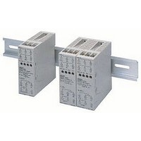
Side-by-side Mounting
Note: Use the PFP-M End Plate for a
Relay contact output
Open collector output
• Connect a surge suppressor or diode in parallel to the load if an
• Connect the cathode side of the diode to the
• When using a load (e.g., contactor or valve) that generates an arc
• When using both NO and NC outputs at the same time, incorporate
• When two or more S3D2 are
• If side-by-side mounting is
Relay contact output
inductive load or other electrical part that generates noise is
connected to the output.
supply.
when the circuit is broken, the NC (NO) contact may turn ON before
the NO (NC) contact has opened (turned OFF).
an arc suppressor (use the CR method, varistor, or other
countermeasure).
mounted side by side, be sure
to provide a minimum distance
of 10 mm between them.
unavoidable, refer to the following load derating curve.
space of 10 mm.
Load current (mA)
Surge suppressor
Diode
L
L
200
100
0
AC power supply
DC power supply
10
Surge suppressor
Range in which
side-by-side
mounting is
possible
10 mm
20 25 30
Diode
Ambient temperature (°C)
side of the power
Resistance: 50 Ω
Capacitor: 0.4 µF
Voltage: 200 V
Peak reverse
breakdown voltage is
at least three times
the load voltage.
Average rectified
current: 1 A
40
S3D2
S3D2
DIN Track
50 55 60
End Plate
(PFP-M)
7
Related parts for S3D2-AK-US
Image
Part Number
Description
Manufacturer
Datasheet
Request
R

Part Number:
Description:
SEN CTR SPDT NPN NO/TMR
Manufacturer:
Omron
Datasheet:
Part Number:
Description:
PNP IN, REL OUT TIMERS
Manufacturer:
Omron
Datasheet:

Part Number:
Description:
Sensor Controller
Manufacturer:
Omron Corporation
Datasheet:
Part Number:
Description:
G6S-2GLow Signal Relay
Manufacturer:
Omron Corporation
Datasheet:
Part Number:
Description:
Compact, Low-cost, SSR Switching 5 to 20 A
Manufacturer:
Omron Corporation
Datasheet:
Part Number:
Description:
Manufacturer:
Omron Corporation
Datasheet:
Part Number:
Description:
Manufacturer:
Omron Corporation
Datasheet:
Part Number:
Description:
Manufacturer:
Omron Corporation
Datasheet:
Part Number:
Description:
Manufacturer:
Omron Corporation
Datasheet: