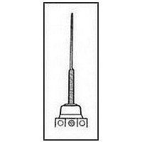
AZ8169 PANASONIC EW, AZ8169 Datasheet - Page 4

AZ8169
Manufacturer Part Number
AZ8169
Description
LIMIT SW, WOBBLE COIL SPRING LEVER, SPDT
Manufacturer
PANASONIC EW
Datasheet
1.AZ8104.pdf
(24 pages)
Specifications of AZ8169
Actuator Style
Wobble Coil Spring Lever
Operating Force Max
0.88N
Contact Voltage Ac Max
250V
Contact Voltage Dc Max
125V
Contact Current Ac Max
5A
Contact Current Dc Max
400mA
Lead Free Status / RoHS Status
Lead free / RoHS Compliant
VL (AZ8)
SPECIFICATIONS
1. Rating
1) Standard type
2. Characteristics
3. EN60947-5-1 performance
4. Operating characteristics
*Characteristics measured at bent condition: min. radius 100mm 3.937inch.
Notes) 1. Keep the total travel values in the specified range. Otherwise the actuator force may rise to several times the operating force, resulting in a mechanical failure or much shorter service life.
5. Protective construction
DATA
1. Life curve
54
Rated control voltage
Actuator
Contact arrangement
Initial contact resistance, max.
Contact material
Initial insulation resistance (At 500V DC)
Initial breakdown voltage
Shock resistance max.
Vibration resistance
Expected life (Min. operations)
Ambient temperature/Ambient humidity
Max. operating speed
Push plunger
Roller plunger
Cross roller plunger
Roller arm
Adjustable roller arm
Adjustable rod
Flexible rod spring wire
Protective construction
2. For the operating characteristics, refer to the TECHNICAL INFORMATION.
1000
500
400
300
200
100
Rated insulation voltage (Ui)
Rated impulse withstand voltage (Uimp)
Switching overvoltage
Rated enclosed thermal current (Ithe)
Conditional short-circuit current
Short-circuit protection device
Protective construction
Pollution degree
30
125V AC
250V AC
125V DC
0
IP60
IP64
IEC
Characteristics
Life curve , resistive load
( AC 240VC cos =1 )
Load current , A
Load
Item
7.84 {800}~3.35 {342}
7.84 {800}~1.99 {203}
5
O.F. (N {gf}) max.
VL Mini limit switch
8.83 {900}
5.88 {600}
0.88 {90}
Resistive load
(cos
0.4A
5A
5A
]1)
In the free position
In the full operating position
Mechanical
Electrical
Life of lamp
10
0.49 {50}~0.21 {21}
0.49 {50}~0.12 {12}
R.F. (N {gf}) min.
1.47 {150}
2. Actual load life curve (relay coil load)
Note: The FC magnetic contactor series is 200V AC. The NK
is 2 Form C 24V DC type.
0.49 {50}
VL Mini limit switch
Inductive load
–
(cos ]0.4)
(with lamp)
1000
500
0
0.1A
3A
2A
0.5
NK
HC
1.0
Pretravel (P.T.), max.
1 Form A 1 Form B
15m (By voltage drop 6 to 8V DC at rated current)
Gold clad silver alloy (cadmium free)
Min. 100M
1,000Vrms for 1 min Between non-consecutive terminals 2,000Vrms for 1 min Between
dead metal parts and each terminal 2,000Vrms for 1 min Between ground and each terminal
Max. 98m/s
Max. 294m/s
Standard type: Max. 55Hz Type with indicator: 10 to 50Hz, double amplitude of 1.5mm
10
3
Min. 2 10
–20 to +60°C
120 cpm
Various relay loads ( VA )
HP
7
3
10
(at 120 cpm)
HG
30 (1.181)
5
5
mm
1.5
(at rated resistive load) 5 10
10A fuse
250VAC
Rating
2.5kV
2.5kV
100A
20°
20°
20°
IP64
VC-20
5A
.059
4
inch
3
2) Types with neon lamp and with LED
6.Lamp rating
2
hours (Neon lamp type)
{10G}
2
Neon lamp
{30G}
–4 to
With Neon lamp
Types
FC-10
LED
50
With LED
Types
+140°F/Max. 95%
FC-35
Movement Differential
(M.D.), max. mm
260
Rated operating voltage Operating voltage range
100 to 200V AC
FC-100
700
24 to 48V DC
0.7
10°
10°
10°
12V DC
6V DC
–
.028
6
Rated control
(Magnetic contactor FC-100 200V AC load)
125V AC
240V AC
24V DC
voltage
WIRING DIAGRAM
Output circuit
Terminal
inch
Overtravel (O.T.), min.
80 to 240V AC
20 to 55V DC
5 to 15V DC
9 to 28V DC
20 (.787)
mm
4
75°
75°
75°
Resistive load
.028
inch
(cos ]1)
N.O.
N.C.
5A
5A
3A
13
11
13
11
Totaltravel (T.T.), min.
Internal resister
VL
Inductive load
50 (1.969)
(cos ]0.4)
mm
5.5
120k
2.4k
4.7k
15k
95°
95°
95°
.217
inch
3A
2A
–
14
12
14
12
N.O.
N.C.


