D4NH3132H Omron, D4NH3132H Datasheet - Page 9
D4NH3132H
Manufacturer Part Number
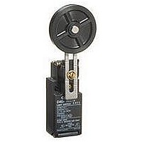
D4NH3132H
Description
LIMIT SWITCH, SPDT-1NO/1NC
Manufacturer
Omron
Series
D4NHr
Datasheet
1.D4NH3132H.pdf
(13 pages)
Specifications of D4NH3132H
Contact Voltage Ac Max
240V
Contact Voltage Dc Max
250V
Contact Current Ac Max
10A
Contact Current Dc Max
2.5A
Switch Terminals
Screw
Contact Configuration
SPDT-1NO / 1NC
Circuitry
SPDT-1NO/1NC
Lead Free Status / RoHS Status
na


Safety Precautions
Refer to the “Precautions for All Switches” and “Precautions for All Safety Door Switches”.
Mounting Method
Appropriate Tightening Torque
Switch Mounting
Electric shock may occasionally occur.
Do not use metal connectors or metal conduits.
• Do not use the Switch submerged in oil or water, or in locations
• Always attach the cover after completing wiring and before using
• Do not switch circuits for two or more standard loads (250 VAC,
• Loose screws may result in malfunction. Tighten the screws to the
Terminal screw
Cover mounting screw
Head mounting screw
Arm lever mounting screw
Body mounting screw
Connector, M12 adaptor
Cap screw
• When loosening a screw with an electrical screwdriver or similar
• Mount the Switch using M4 screws and spring washers and tighten
• To ensure safety, use screws that cannot be easily removed or
• As shown below, two studs with a maximum height of 4.8 mm and
continuously subject to splashes of oil or water. Doing so may
result in oil or water entering the Switch interior. (The IP67 degree
of protection specification for the Switch refers to water penetration
while the Switch is submersed in water for a specified period of
time.)
the Switch. Also, do not turn ON the Switch with the cover open.
Doing so may result in electric shock.
3 A) at the same time. Doing so may adversely affect insulation
performance.
specified torques.
tool while pressing down on the screw head, do not continue
turning the screw past the point where the threads disengage.
Doing so may strip the end of the threads.
the screws to the specified torque.
another means to prevent the Switch and Operation Key from
easily being removed.
a diameter of 4
holes on the bottom of the Switch, and the Switch secured at four
locations to increase the mounting strength.
Precautions for Correct Use
Precautions for Safe Use
−0.05
−0.15
mm can be provided, the studs inserted into the
!CAUTION
0.6 to 0.8 N·m
0.5 to 0.7 N·m
0.5 to 0.6 N·m
1.6 to 1.8 N·m
0.5 to 0.7 N·m
1.8 to 2.2 N·m
1.4 to 1.8 N·m (1/2-14NPT)
1.3 to 1.7 N·m
Switch Mounting Holes
• One-conduit Type
Be sure that the arm lever and door are mounted as shown in the
following diagram so that the arm lever and head are not subjected to
mechanical stress when the door opens or closes.
• Two-conduit Type
• Mount the shaft or arm lever securely with a
• Align the rotational center of the shaft with the
one-way screw, or an equivalent so that the
shaft or arm lever cannot be easily removed.
door, so that the Switch shaft and head will not
be subjected to mechanical stress when the
door opens or closes.
Do not impose a force of 50 N or more on the
shaft.
5.35±
8 to 10 dia.
0.1
2.5±
39±
2.5±
47±
0.1
0.1
0.1
0.1
1 to 3
1 to 3
Two, M4
Two, M4
20±
22±
22±
20±
22±
40±
42±
42±
0.1
0.1
0.1
0.1
0.1
0.1
0.1
0.1
4.5 to 5 dia.
4
Height: 4.8 max.
−0.05
−0.15
dia.
4
Height: 4.8 max.
−0.05
−0.15
dia.
D4NH
9
Related parts for D4NH3132H
Image
Part Number
Description
Manufacturer
Datasheet
Request
R

Part Number:
Description:
LIMIT SWITCH, ROLLER LEVER
Manufacturer:
Omron
Datasheet:

Part Number:
Description:
LIMIT SWITCH, 1WAY, ROLLER ARM
Manufacturer:
Omron
Datasheet:

Part Number:
Description:
LIMIT SW, ADJUSTABLE ROLLER LEVER, SPDT
Manufacturer:
Omron
Datasheet:

Part Number:
Description:
G6S-2GLow Signal Relay
Manufacturer:
Omron Corporation
Datasheet:
Part Number:
Description:
Compact, Low-cost, SSR Switching 5 to 20 A
Manufacturer:
Omron Corporation
Datasheet:
Part Number:
Description:
Manufacturer:
Omron Corporation
Datasheet:
Part Number:
Description:
Manufacturer:
Omron Corporation
Datasheet:
Part Number:
Description:
Manufacturer:
Omron Corporation
Datasheet:
Part Number:
Description:
Manufacturer:
Omron Corporation
Datasheet:
Part Number:
Description:
Manufacturer:
Omron Corporation
Datasheet: