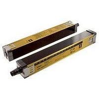
F3SN-A0607P25 Omron, F3SN-A0607P25 Datasheet - Page 18

F3SN-A0607P25
Manufacturer Part Number
F3SN-A0607P25
Description
Safety Light Curtain
Manufacturer
Omron
Datasheet
1.F3SN-A0207P14.pdf
(40 pages)
Specifications of F3SN-A0607P25
Beam Spacing
15mm
Control Output Type
PNP
No. Of Beams
39
Protection Height
607mm
Sensing Range Max
10m
Supply Voltage Max
24VDC
Peak Reflow Compatible (260 C)
No
Light Curtain Type
Safety
Lead Free Status / RoHS Status
Contains lead / RoHS non-compliant
Function
* These indicators flash to indicate the need for preventive maintenance when the total ON time exceeds 30,000 hours. (Models without this
Engineering Data (Typical Examples)
Parallel operating range
F3SN-A1107P14
Power indicator
Interlock indicator
Lockout indicator
Test indicator
ON-state indicator
OFF-state indicator
Blanking indicator (F3SN-A only)
Optional function indicator
(F3SN-B only)
Light intensity level indicator
Error mode indicator
−100
−200
−300
flashing function are also available as options. An “-NT” to the model number. Ask your OMRON representative for details.)
Horizontal direction
300
200
100
0
Positive vertical
direction
X
2
Negative vertical
direction
Flashing
Y
Positive horizontal
direction
Lit
4
Negative
horizontal direction
http://www.ia.omron.com/
Not lit
Not lit
Vertical direction
6
Distance X (m)
X
8
1
A
10
2
B
Y
Lit when power is supplied (always lit):
Lit when power is supplied, flashing when the F39-MC11 is connected: F3SH-A Receiver *
Lit during interlock condition
Flashing during lockout condition
Lit during external test *
Lit when OSSD outputs are in ON-state
Lit when OSSD outputs are in OFF-state
Lit when blanking is set, flashing when the F39-MC11 is connected *
Flashing after a lapse of 30,000 hours
C
3
Angular range
(Angle of elevation)
F3SN-A1107P14
−1
−2
−3
−4
4
4
3
2
1
0
The Interlock selection input line or the reset input line is not wired correctly or became
open.
Relay contact is welded. Releasing time of the relay takes too long.
The EDM input line is not wired correctly or became open.
Communication line (RS-485) is not wired correctly, became open, or causes other errors.
One of the OSSD outputs is shorted or is not wired correctly.
Other failure in OSSD outputs.
Mutual interference. Interference light is received.
Types of the receiver and emitter are not the same.
Numbers of the receiver and emitter connected in series are not the same.
External noise. Internal hardware failure of the receiver or the emitter.
5
Negative direction
for emitter
Negative direction
for receiver
Positive direction
for emitter
Positive direction
for receiver
2
200% and above of ON threshold level
150 to 200% of ON threshold level
100 to 150% of ON threshold level
75 to 100% of ON threshold level
50 to 75% of ON threshold level
Less than 50% of ON threshold level
θ
X
4
Light intensity level
(c)Copyright OMRON Corporation 2007 All Rights Reserved.
Distance X (m)
6
Cause of error
8
F3SN-A/F3SN-B/F3SH-A
Angular range
(Angle of rotation)
F3SN-A1107P14
−1
−2
−3
−4
4
3
2
1
0
Negative direction
for emitter
Negative direction
for receiver
Positive direction
for receiver
Positive direction
for emitter
F3SN-A, F3SH-A Emitter
2
θ
X
4
Distance X (m)
6
8
18


