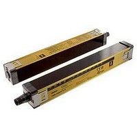
F3SN-A0607P25 Omron, F3SN-A0607P25 Datasheet - Page 26

F3SN-A0607P25
Manufacturer Part Number
F3SN-A0607P25
Description
Safety Light Curtain
Manufacturer
Omron
Datasheet
1.F3SN-A0207P14.pdf
(40 pages)
Specifications of F3SN-A0607P25
Beam Spacing
15mm
Control Output Type
PNP
No. Of Beams
39
Protection Height
607mm
Sensing Range Max
10m
Supply Voltage Max
24VDC
Peak Reflow Compatible (260 C)
No
Light Curtain Type
Safety
Lead Free Status / RoHS Status
Contains lead / RoHS non-compliant
Connection Circuit Examples
An Example of Safety Circuits Where No Controller Is Used
For Category 4 Rating (F3SN-A, F3SH-A)/Category 2 Rating (F3SN-B)
An Example of Safety Circuits Where the G9SA-301 Safety Relay Unit is Connected
For category 4 rating (F3SN-A, F3SH-A)/category 2 rating (F3SN-B)
E1
+24 VDC
0 V
G9SA-301
A1
S1
S1
E1
A2
+24 VDC
S2
Emitter
T11
PE
0 V
Emitter
a
K1
T21
K1
http://www.ia.omron.com/
T12
6
b
K2
T23
RS-485(A) (Gray)
RS-485(B) (Pink)
RS-485(A) (Gray)
RS-485(B) (Pink)
K2
T22
a
b
S2
1
T31
Control
A
Circuit
K1
K2
T32
B
KM1
KM2
3
4
2
5
Receiver
Receiver
KM1
KM1
KM2
13
14
PLC
IN
23
24
12
11
KM1 KM2
KM2
33
34
22
21
41
42
OUT
JP
Applicable operation mode
• For sensor
• For safety relay unit
• Use the emergency stop switch *2
1
2
3
4
5
6
*2
S3
• Manual reset mode
• Use the feedback loop
• Auto-reset mode
• Disable the EDM monitor function
(by setting on the F39-MC11, *1.)
PLC
IN1
IN2
OUT
M
KM1
KM2
KM3
M
S1:
S2:
KM1, KM2: Safety relay with forcibly guided contacts (G7SA) or
KM3:
M:
E1:
PLC:
Applicable operation mode
• Manual reset mode
• Using the EDM function
(c)Copyright OMRON Corporation 2007 All Rights Reserved.
KM3
KM1
KM2
External test switch
Interlock/lockout reset switch
magnetic contactor
Solid-state contactor (G3J)
3-phase motor
24 VDC power supply (S82K)
Programmable controller
(Used for monitoring. This is not a part of a safety system.)
*1. The F39-MC11 setting console cannot be
*2. If emergency stop switch is not necessary,
S1:
S2:
S3:
KM1, KM2: Magnetic contactor
KM3:
M:
E1:
PLC:
Timing Chart
Emergency stop switch
Timing Chart
External test switch
External test switch
Light interrupted
connected to the F3SN-B. Therefore, short-
circuit the auxiliary output terminal and the
EDM input.
connect the OSSD 1 directly to T12 terminal
and connect the OSSD 2 directly to T23
terminal.
F3SN-A/F3SN-B/F3SH-A
Light interrupted
Light incident
Reset switch
KM1, KM2
N.O. contact
KM1, KM2
N.C. contact
PLC input *
PLC output
Light incident
Reset switch
K1, K2
N.O. contact
KM1, KM2
N.O. contact
K1, K2
N.C. contact
KM1, KM2
N.C. contact
PLC input 1
PLC input 2
PLC output
OSSD
(S1)
(S2)
OSSD
External test switch
Reset switch
Emergency stop switch
(direct opening contacts)
(A165E or A22E)
Solid-state contactor (G3J)
3-phase motor
24 VDC power supply (S82K)
Programmable controller
(Used for monitoring.
This is not a part of a safety system.)
(S1)
(S2)
(S3)
* The output operation mode of the auxiliary
output is the Dark-ON output mode.
Depends on the operation mode of the auxiliary output
26


