HS6E-P44B03-G IDEC, HS6E-P44B03-G Datasheet - Page 9
HS6E-P44B03-G
Manufacturer Part Number
HS6E-P44B03-G
Description
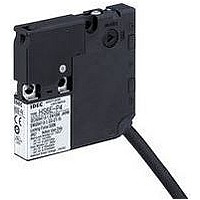
SWITCH, SAFETY INTERLOCK, 2NC, 2A
Manufacturer
IDEC
Series
HS6Er
Datasheet
1.HS6E-L44B03-G.pdf
(20 pages)
Specifications of HS6E-P44B03-G
Contact Voltage Ac Max
125V
Contact Voltage Dc Max
30V
Contact Current Ac Max
2A
Contact Current Dc Max
2A
Switch Terminals
Cable
Contact Configuration
SPST-NC / SPST-NC
Rohs Compliant
Yes
Lead Free Status / RoHS Status
Lead free / RoHS Compliant


(07/03/12)
Dimensions
• Actuator Mounting Reference Position
As shown in the figure on the right, the mounting reference position of the actuator
when inserted in the interlock switch is:
The actuator stop on the actuator lightly touches the interlock switch.
Note: After mounting the actuator, remove the actuator stop from the actuator.
• • • • Interlock Switch
When using straight actuator
(HS9Z-A61)
(12.6
(5)
HS6E Subminiature Interlock Switches with Solenoid
46.1
41.8
±1
)
37
1
Actuator Stop
(supplied)
28.5
10.1
5.5
20
15
1
When using right-angle actuator
(HS9Z-A62S)
(22.5)
Note: 41.4 when using HS9Z-A62.
The tensile strength of the HS9Z-A62 actuator is
100N. When tensile force exceeding 100N is
expected, use the HS9Z-A62S actuator, which
has a mounting plate.
4
(22.5)
22.6
4
±1
Manual Unlocking Key
• • • • Mounting Hole Layout
3-M4 Screw
(ø4.3 or M4 tapped hole)
Actuator Stop
(supplied)
20 to 22
(14)
Hole for Manual Unlocking
ø12 (reference)
HS9Z-A61 Actuator
Interlock Switch
Actuator Stop
41.8
When using horizontal/vertical
angle adjustable actuator
(HS9Z-A65/A66)
28.5
28.5
22.6
±1
Hole for Manual Unlocking
ø12 (reference)
41.8
(25)
3-M4 Screw
(ø4.3 or M4 tapped hole)
Actuator Stop
(supplied)
20 to 22
Door Stop
Door Stop
9
Related parts for HS6E-P44B03-G
Image
Part Number
Description
Manufacturer
Datasheet
Request
R

Part Number:
Description:
SWITCH, SAFETY INTERLOCK, 2NC, 2A
Manufacturer:
IDEC
Datasheet:
Part Number:
Description:
SWITCH, SAFETY INTERLOCK, 2NC, 2A
Manufacturer:
IDEC
Datasheet:
Part Number:
Description:
SWITCH, SAFETY INTERLOCK, 2NC, 2A
Manufacturer:
IDEC
Datasheet:
Part Number:
Description:
SWITCH, SAFETY INTERLOCK, 2NC, 2A
Manufacturer:
IDEC
Datasheet:
Part Number:
Description:
SWITCH, SAFETY INTERLOCK, 2NC, 2A
Manufacturer:
IDEC
Datasheet:
Part Number:
Description:
SWITCH, SAFETY INTERLOCK, 2NC, 2A
Manufacturer:
IDEC
Datasheet:
Part Number:
Description:
SWITCH, SAFETY INTERLOCK, 2NC, 2A
Manufacturer:
IDEC
Datasheet:

Part Number:
Description:
Safety Switch Solenoid Lock 1m
Manufacturer:
IDEC
Datasheet:
Part Number:
Description:
Cable; Between IDEC MicroSmart (port 1 or 2) and HG2F/3F/4F; 5 ft.
Manufacturer:
IDEC Corporation
Datasheet:
Part Number:
Description:
Cable; Between IDEC Micro^3C/ONC/MicroSmart (port 2) PLCs and HG2F/3F/4F; 5 ft.
Manufacturer:
IDEC Corporation
Datasheet:
Part Number:
Description:
INDICATOR INCANDESCENT LAMP, GREEN
Manufacturer:
IDEC
Datasheet:

Part Number:
Description:
LAMP, INDICATOR, INCAND, AMB
Manufacturer:
IDEC
Datasheet:
Part Number:
Description:
LAMP, INDICATOR, INCAND, GRN
Manufacturer:
IDEC
Datasheet:
Part Number:
Description:
LAMP, INDICATOR, INCAND, GRN
Manufacturer:
IDEC
Datasheet:
Part Number:
Description:
LAMP, INDICATOR, INCANDESCENT, RED
Manufacturer:
IDEC
Datasheet: