H3DE-M1 Omron, H3DE-M1 Datasheet - Page 3
H3DE-M1
Manufacturer Part Number
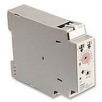
H3DE-M1
Description
Multifunction Timer
Manufacturer
Omron
Datasheet
1.H3DE-S2.pdf
(14 pages)
Specifications of H3DE-M1
Time Range
0.1 - 120 Hr
Height
79mm
Voltage Ac
250V
External Width
22.5mm
Voltage Rating Vdc
30V
Timing Function
Multifunction
External Depth
100mm
Operating Temperature Min
-10°C


H3DE-M/-S
Note: 1. With the H3DE-M , if the voltage exceeds 26.4 VAC/DC, the following hold at signal OFF for C, D, and G modes:
Accuracy of operating time
Setting error
Signal input time
Influence of voltage
Influence of temperature
Insulation resistance
Dielectric strength
Vibration resistance
Shock resistance
Contact material
Impulse withstand voltage
Noise immunity
Static immunity
Life expectancy
EMC
Enclosure rating
Weight
Characteristics
2. For reference : A maximum current of 0.15 A can be switched at 125 VDC (cos =1).
Accuracy of operating time: 1% 50 ms max. at 1.2-s range
Setting error: 10% +100/–50 ms max.
Signal input time: 100 ms min.
A maximum current of 0.1 A can be switched if L/R is 7 ms.
In both cases, a life of 100,000 operations can be expected.
The minimum applicable load is 10 mA at 5 VDC (failure level: P).
50 ms min. (see note 1)
100 M min. at 500 VDC
Between current-carrying metal parts and exposed non-current-carrying metal parts:
2,000 VAC for 1 min.
Between control output terminals and operating circuit: 2,000 VAC for 1 min.
Between contacts of different polarities: 2,000 VAC for 1 min.
Between contacts not located next to each other: 1,000 VAC for 1 min.
Malfunction: 0.5-mm single amplitude at 10 to 55 Hz
Destruction: 0.75-mm single amplitude at 10 to 55 Hz
Malfunction: 100 m/s
Destruction: 1,000 m/s
AGNi+gold plating (Use the G6RN-1 at 12 VDC.)
3 kV (between power terminals)
4.5 kV (between current-carrying metal parts and exposed non-current-carrying metal parts)
Square-wave noise generated by noise simulator (pulse width: 100 ns/1 s, 1-ns rise) 1.5 kV
Malfunction: 4 kV
Destruction: 8 kV
Mechanical: 10 million operations min. (under no load at 1,800 operations/h)
Electrical:
(EMI):
Emission Enclosure:
Emission AC Mains:
Harmonic Current:
Voltage Fluctuation and Flickering: EN61000-3-3
(EMS):
Immunity ESD:
Immunity RF-interference from AM Radio Waves:
Immunity RF-interference from Pulse-modulated Radio Waves:
Immunity Conducted Disturbance:
Immunity Burst:
IP30 (Terminal block: IP20)
120 g
1% max. of FS ( 1% 10 ms max. at 1.2-s range) (see note 1)
10% 50 ms max. of FS (see note 1)
0.5% max. of FS ( 0.5% 10 ms max. at 1.2-s range)
2% max. of FS ( 2% 10 ms max. at 1.2-s range)
100,000 operations min. (5 A at 250 VAC, resistive load at 360 operations/h)
(see note 2)
2
(approximately 10G)
2
(approximately 100G)
EN50081-1
EN55022 class B
EN55022 class B
EN61000-3-2
EN50082-2
EN61000-4-2:4 kV contact discharge (level 2)
ENV50140:
ENV50204:
ENV50141:
EN61000-4-4:2 kV power line (level 3)
8 kV air discharge (level 3)
10 V/m (80 MHz to 1 GHz) (level 3)
10 V/m (900 5 MHz) (level 3)
10 V (0.15 to 80 MHz) (level 3)
2 kV I/O signal line (level 4)
H3DE-M/-S
7
Related parts for H3DE-M1
Image
Part Number
Description
Manufacturer
Datasheet
Request
R

Part Number:
Description:
RELAY TIMER ANALOG DIN 4 MODE
Manufacturer:
Omron
Datasheet:

Part Number:
Description:
RELAY TIMER ANALOG DIN 8 MODE
Manufacturer:
Omron
Datasheet:

Part Number:
Description:
RELAY TIMER ANALOG DIN 4 MODE
Manufacturer:
Omron
Datasheet:

Part Number:
Description:
RELAY TIMER ANALOG DIN 8 MODE
Manufacturer:
Omron
Datasheet:

Part Number:
Description:
TIMER STAR-DELTA 22.5MM DIN MNT
Manufacturer:
Omron
Datasheet:

Part Number:
Description:
TIMER 22.5MM 1-120S DIN MNT
Manufacturer:
Omron
Datasheet:
Part Number:
Description:
TIMER 22.5MM .1-12S DIN MNT
Manufacturer:
Omron
Datasheet:
Part Number:
Description:
TIMER 22.5MM .1-12S DIN MNT
Manufacturer:
Omron
Datasheet:
Part Number:
Description:
TIMER 22.5MM 1-120S DIN MNT
Manufacturer:
Omron
Datasheet:

Part Number:
Description:
TIMER DIN MNT 22.5mm
Manufacturer:
Omron
Datasheet:

Part Number:
Description:
G6S-2GLow Signal Relay
Manufacturer:
Omron Corporation
Datasheet:
Part Number:
Description:
Compact, Low-cost, SSR Switching 5 to 20 A
Manufacturer:
Omron Corporation
Datasheet:
Part Number:
Description:
Manufacturer:
Omron Corporation
Datasheet: