H5CX-L8D-N AC24/DC12-24 Omron, H5CX-L8D-N AC24/DC12-24 Datasheet - Page 28
H5CX-L8D-N AC24/DC12-24
Manufacturer Part Number
H5CX-L8D-N AC24/DC12-24
Description
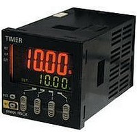
Digital Multifunction Timer
Manufacturer
Omron
Datasheet
1.Y92P-CXT4B.pdf
(44 pages)
Specifications of H5CX-L8D-N AC24/DC12-24
Time Range
0.001s-9999hrs
Power Consumption
2.4W
Reset Time
20ms
Character Size
11.5mm
Time Range Min
0.001s
Supply Voltage Min
12V
Connector Type
8-Pin Socket
Signal Input Type
PNP/NPN
No. Of Digits / Alpha
4
Rohs Compliant
Yes
Lead Free Status / RoHS Status
Lead free / RoHS Compliant
For Use With
PNP/NPN


28
H5CX-A@-N/-L@-N
Twin Timer
Explanation of Functions
Operating Procedures for Twin Timer Function
Items marked with stars ( ) can be set using the DIP switch.
OFF Time Range (oftr)
Set the time range for the OFF time in the range 0.000 s to 9,999 h.
Only settings of type --.-- s (99.99 s), ---.- s (999.9 s), ---- s (9,999 s),
and -- min -- s (99 min 59 s) can be made with the DIP switch. Use the
operation keys if another type of setting is required.
ON Time Range (ontr)
Set the time range for the ON time in the range 0.001 s to 9,999 h.
Only settings of type --.-- s (99.99 s), ---.- s (999.9 s), ---- s (9,999 s),
and -- min -- s (99 min 59 s) can be made with the DIP switch. Use the
operation keys if another type of setting is required.
Timer Mode (timm)
Set either the elapsed time (UP) or remaining time (DOWN) mode.
In UP mode, the elapsed time is displayed, and in DOWN mode, the
remaining time is displayed.
ON/OFF Start Mode (totm)
Set the output mode.
Set either flicker OFF start or flicker ON start. (For details on output
mode operation, refer to "Timing Charts" on page 29.)
Input Signal Width (iflt)
Set the minimum signal input width (20 ms or 1 ms) for signal, reset,
and gate inputs.
The same setting is used for all external inputs (signal, reset, and gate
inputs).
If contacts are used for the input signal, set the input signal width to
20 ms.
Processing to eliminate chattering is performed for this setting.
Operation in Run Mode
Operating Procedures for Twin Timer Function
Present Value and OFF Set Time
The present value is displayed in the main display and the OFF set
time is displayed in the sub-display. Set the OFF time.
Note: 1. The display will automatically show the OFF set time when the OFF time is being timed and the ON set time when the ON time is being timed.
Note: 2. H5CX-L8E@-N Precautions
Set the Timer’s set value before using the Timer in a self-holding circuit.
Present value
OFF set time
Present value
ON set time
Set the digits for the OFF set time using the corresponding
Set the digits for the OFF set time using the corresponding
NPN/PNP Input Mode (imod)
Select either NPN input (no-voltage input) or PNP input (voltage input)
as the input format. Set an NPN input when using a 2-wire sensor.
The same setting is used for all external inputs.
For details on input connections, refer to "Input Connections" on
page 9.
Display Color (colr)
(Terminal black model: H5CX-A@ only)
Set the color used for the present value.
Key Protect Level (kypt)
Set the key protect level.
Refer to “Key Protect Level” on page 32.
Present Value and ON Set Time
The present value is displayed in the main display and the ON set
time is displayed in the sub-display. Set the ON time.
red
grn
org
r-g
g-r
r-o
o-r
g-o
o-g
Output OFF
Orange
Orange
Green
Green
Red
Red
keys.
keys.
Orange (fixed)
Green (fixed)
Red (fixed)
Output ON
Orange
Orange
Green
Green
Red
Red
Related parts for H5CX-L8D-N AC24/DC12-24
Image
Part Number
Description
Manufacturer
Datasheet
Request
R

Part Number:
Description:
Relay; E-Mech; Timing; Multi-Function; Cur-Rtg 5A; Ctrl-V 24/12-24AC/DC; Socket Mnt
Manufacturer:
Omron Automation
Datasheet:

Part Number:
Description:
8-PIN, RLY OUT, Limit, Instant DC12-24/AC24
Manufacturer:
Omron
Datasheet:
Part Number:
Description:
G6S-2GLow Signal Relay
Manufacturer:
Omron Corporation
Datasheet:
Part Number:
Description:
Compact, Low-cost, SSR Switching 5 to 20 A
Manufacturer:
Omron Corporation
Datasheet:
Part Number:
Description:
Manufacturer:
Omron Corporation
Datasheet:
Part Number:
Description:
Manufacturer:
Omron Corporation
Datasheet:
Part Number:
Description:
Manufacturer:
Omron Corporation
Datasheet:
Part Number:
Description:
Manufacturer:
Omron Corporation
Datasheet:
Part Number:
Description:
Manufacturer:
Omron Corporation
Datasheet:
Part Number:
Description:
Manufacturer:
Omron Corporation
Datasheet: