Tel +1 (717) 767-6511
Fax +1 (717) 764-0839
www.redlion.net
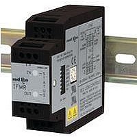
MODEL IFMR - DIN-RAIL SPEED SWITCH
DESCRIPTION
(SPDT) based on the value of the input frequency. The Trip frequency can be
set to any value from 0.1 Hz to 25 KHz. The IFMR can be set to trip on
overspeed, or underspeed (including zero speed). Offset and hysteresis values
can be incorporated into the trip setting to eliminate output chatter. LED
indicators for both the Input signal and the Relay status are provided. Two
separate input connections for external push-buttons are also provided. One
external input overrides the trip detection function, and holds the relay in the
release state as long as the input is pulled to common. The other external input
clears a latched trip condition when pulled to common.
button and two indication LEDs to accomplish input circuit configuration,
operational parameter set-up, input signal, and relay status indication. The input
circuitry is DIP switch selectable for a variety of sources.
signal and relay status of the IFMR. These LEDs are also used to provide visual
feedback to the user of the current parameter settings during parameter set-up.
DIMENSIONS In inches (mm)
installation and operation of the unit.
Read complete instructions prior to
The Model IFMR accepts a frequency input, and controls a single relay
The IFMR utilizes a seven position DIP switch, a rotary switch, a push-
The indication LEDs are used during normal operation to display the input
CAUTION: Risk of Danger.
(79.2)
3.12
0
5
M1865G
CAUTION: Risk of electric shock.
(27.5)
1.08
IFMR
OUT
IN
M1864G
S
T
A
T
U
S
1
ORDERING INFORMATION
programmable Minimum Response Time provides optimum response vs. input
filtering for any input frequency. The offset and hysteresis settings provide
flexible adjustment of the relay trip and release points.
standard DIN style mounting rails, including top hat profile rail according to EN
50 022 - 35 x 7.5 and 35 x 15, and G profile rail according to EN 50 035 - G32.
SAFETY SUMMARY
manual or on equipment must be observed to ensure personal safety and to
prevent damage to either the instrument or equipment connected to it. If
equipment is used in a manner not specified by the manufacturer, the protection
provided by the equipment may be impaired.
SPECIFICATIONS
1. POWER:
2. SENSOR POWER: (AC version only) +12 VDC 25% @ 60 mA max.
3. OPERATING FREQUENCY RANGE: 0 Hz to 25 KHz
4. SIGNAL INPUT: DIP switch selectable to accept signals from a variety of
SIMPLE ON-LINE TRIP FREQUENCY SETTING (USING ACTUAL
USER SETTABLE TRIP FREQUENCY FROM 0.1 Hz to 25 KHz
OVER-SPEED, UNDER-SPEED, AND ZERO-SPEED DETECTION
RELAY LATCHING, ALARM OVERRIDE, AND ALARM RESET
PROGRAMMABLE INPUT CIRCUIT ACCEPTS OUTPUTS FROM
HYSTERESIS AND OFFSET FUNCTIONS AVAILABLE
85 to 250 VAC and 9 to 32 VDC VERSIONS AVAILABLE
INPUT AND RELAY STATUS INDICATION LED’S
MODEL NO.
The IFMR operates in one of six output modes, as selected by the user. The
The unit is equipped with a universal mounting foot for attachment to
All safety related regulations, local codes and instructions that appear in the
or the installation of guards, shields, or other devices to protect personnel in
the event of a hazardous machine speed condition. The speed switch may be
installed to help prevent the machine from entering the unsafe speed.
AC Powered Versions: 85 to 250 VAC; 48 to 62 Hz; 5.5 VA
DC Powered Versions: 9 to 32 VDC; 2.0 W
sources, including switch contacts, outputs from CMOS or TTL circuits,
magnetic pickups, and all standard RLC sensors.
Current Sourcing: Internal 1 K pull-down resistor for sensors with current
Current Sinking: Internal 3.9 K pull-up resistor for sensors with current
Low Bias: Input trigger levers V
Hi Bias: Input trigger levels V
Max. Input Signal: ±90 V; 2.75 mA max. (with both Current Sourcing and
INPUT SIGNAL OR FREQUENCY GENERATOR)
FUNCTIONS
A VARIETY OF SENSORS
IFMR
Power Up Current: Ip = 600 mA for 50 msec max.
sourcing output. (Max. sensor output current = 24 mA @ 24 V output.)
sinking output. (Max. sensor current = 3 mA.)
sensitivity when used with magnetic pickups.
Current Sinking resistors switched off).
WARNING: SPEED SWITCHES MUST NEVER BE USED AS
PRIMARY PROTECTION AGAINST HAZARDOUS OPERATING
CONDITIONS. Machinery must first be made safe by inherent design,
Speed Switch
DESCRIPTION
UL Recognized Component,
File # E137808
IL
= 2.5 V, V
PART NUMBERS FOR AVAILABLE
IL
9 to 32 VDC
IFMR0036
= 0.25 V, V
SUPPLY VOLTAGES
IH
= 3.0 V; for logic level signals.
IH
85 to 250 VAC
= 0.75 V; for increased
IFMR0066
Bulletin No. IFMR-J
Drawing No. LP0341
Released 04/09