IFMR0066 Red Lion Controls, IFMR0066 Datasheet - Page 2
IFMR0066
Manufacturer Part Number
IFMR0066
Description
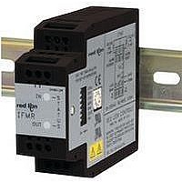
Isolation Amplifier
Manufacturer
Red Lion Controls
Type
Speedr
Datasheet
1.IFMR0036.pdf
(8 pages)
Specifications of IFMR0066
Width
3.12"
Signal Input Type
Selectable Current Or Voltage
Configuration Setup
DIP Switch
Supply Voltage Max
250VAC
Iso-amp Mounting Type
DIN Rail
Display Alarm Type
Relay
Input Accuracy
± 0.1% Of FS
Application
The IFMR utilizes a seven position DIP switch, a rotary switch, a pushbutton and two indication LEDs to accomplish input circuit configuration, operational parameter set-up, input signal, and relay status indication
Brand/series
IFMR Series
Contact Form
SPDT
Current Rating
5 A
Dimensions
27.5mmW×4.2mmH×79.2mmD
Display Type
LED
Input Type
Analog
Mounting Type
DIN Rail
Output Type
Relay
Power, Rating
5.5 VA
Primary Type
Controller
Sensor, Input
12 VDC
Standards
cURus, CE
Temperature, Operating
0 to +50 °C
Termination
Screw
Voltage, Rating
85 to 250 VAC
Voltage, Supply
85-250 VAC
Lead Free Status / RoHS Status
Lead free / RoHS Compliant
For Use With
Sensors/Switches/TTL


SPECIFICATIONS (Cont’d)
5. CONTROL INPUTS: Active low (V
6. RELAY CONTACT OUTPUT: FORM “C” (SPDT) contacts max. rating.
7. RELAY LIFE EXPECTANCY: 100,000 cycles at max. rating. (As load
8. ACCURACY: 0.1% of the trip frequency setting.
9. INPUT IMPEDANCE: 33 K min. with the sink and source DIP switches
10. MINIMUM RESPONSE TIME: From 5 msec. +1 period to 10 sec. +1
11. HYSTERESIS AND OFFSET: From 0.25% to 33.33% of Trip Frequency
12. INPUT AND POWER CONNECTIONS: Screw in terminal blocks
13. ISOLATION BREAKDOWN VOLTAGE (Dielectric Withstand):
14. CERTIFICATIONS AND COMPLIANCES:
(AC VERSION ONLY)
VDC through a 100 K resistor (I
Alarm Reset: Unlatches the relay when pulled to common while the input
Alarm Override: Causes the IFMR to unconditionally release the relay
5 A @ 120/240 VAC or 28 VDC (resistive load), 1/8 H.P. @ 120 VAC
(inductive load). The operate time is 5 msec nominal and the release time is
3 msec nominal.
level decreases, life expectancy increases.)
in the OFF positions. (See Block Diagram)
period in ten steps (excluding relay operate time).
in nine steps. Hysteresis and/or Offset can also be set to 0 (Disabled).
2200 V between power & input, and power & output; 500 V between input
& output for 1 minute.
SAFETY
COMMON
OVERRIDE
SENSOR
SUPPLY
ALARM
12 VDC
(60 mA)
SIGNAL
frequency is in the release region.
when pulled to common.
UL Recognized Component, File #E137808, UL508, CSA 22.2 No. 14
IECEE CB Scheme Test Certificate # UL1683A-176645/USA,
ALARM
INPUT
INPUT
RESET
Recognized to U.S. and Canadian requirements under the Component
Recognition Program of Underwriters Laboratories, Inc.
CB Scheme Test Report # 97ME50135-042297
IEC 61010-1, EN 61010-1: Safety requirements for electrical equipment
Issued by Underwriters Laboratories, Inc.
for measurement, control, and laboratory use, Part 1.
4
7
8
9
6
85 to 250
POWER
VAC
AC
100K
+12V
+5V
10
12
S3
SINK
3.9K
1K
S1
SRC
+5V
+5V
SWITCHING
100K
CIRCUIT
10K
SNK
10K
0.1µf
54.9K
8.06K
10.0K
AC
IL
AC VERSION
= 50 μA). Response Time = 1 msec.
33.2K
+5V
= 0.5 V max.) internally pulled up to 5
0.1µf
S2
LOGIC
+12V
0.1µf
470pf
SUPPLY
+
-
POWER
392K
+12V
10K
INPUT
SIGNAL
OVERRIDE
ALARM
RESET
ALARM
PROCESS
CIRCUITRY
BLOCK DIAGRAM
2
RELAY LED
INPUT LED
15. ENVIRONMENTAL CONDITIONS:
16. CONSTRUCTION: Case body is black, high impact plastic. Installation
17. WEIGHT: 6 oz. (0.17 Kg)
BUTTON
RELAY
PUSH
SWITCH
INPUTS
INPUTS
INPUT
ELECTROMAGNETIC COMPATIBILITY
Notes:
1. This device was designed for installation in an enclosure. To avoid
2. For operation without loss of performance:
Refer to the EMC Installation Guidelines section of this bulletin for
Operating Temperature: 0 to 50°C
Storage Temperature: -40 to 80°C
Operating and Storage Humidity: 85% max. (non-condensing) from 0°C to
Vibration according to IEC 68-2-6: Operational 5 to 150 Hz in X, Y, Z
Shock according to IEC 68-2-27: Operational 30 g’s (10 g relay), 11 msec
Altitude: Up to 2000 meters
Category II, Pollution Degree 2
Immunity to EN 50082-2
Electrostatic discharge
Electromagnetic RF fields
Fast transients (burst)
RF conducted interference
Power frequency magnetic fields
Emissions to EN 50081-2
RF interference
BCD
DIP
electrostatic discharge, precautions should be taken when the device is
mounted outside an enclosure. When working in an enclosure (ex. making
adjustments, setting switches, etc.) typical anti-static precautions should
be observed before touching the unit.
Unit is mounted on a rail in a metal enclosure (Buckeye SM7013-0 or
additional information.
50°C.
direction for 1.5 hours, 2 g’s.
in 3 directions.
equivalent) and I/O cables are routed in metal conduit connected to
earth ground.
9 to 32 VDC
INPUT
(GREEN)
MODE
+
CFG2
CFG1
CFG0
-
10
12
SWITCH
S4
S5
S6
S7
BCD
SWITCHING
CIRCUIT
RELAY
(RED)
BUTTON
DC
PUSH
EN 61000-4-2
EN 61000-4-3
EN 61000-4-4
EN 61000-4-6
EN 61000-4-8
EN 55011
DC VERSION
+5V
SUPPLY
POWER
+12V
Level 2; 4 Kv contact
Level 3; 8 Kv air
Level 3; 10 V/m
80 MHz - 1 GHz
Level 4; 2 Kv I/O
Level 3; 2 Kv power
Level 3; 10 V/rms
150 KHz - 80 MHz
Level 4; 30 A/m
Enclosure class A
Power mains class A
2
3
1
N.O.
COMM.
N.C.
2
1
Related parts for IFMR0066
Image
Part Number
Description
Manufacturer
Datasheet
Request
R

Part Number:
Description:
Counter
Manufacturer:
Red Lion Controls
Datasheet:
Part Number:
Description:
Miniature Length Sensor
Manufacturer:
Red Lion Controls
Datasheet:
Part Number:
Description:
Model Lsc - Single Channel Output Length Sensor
Manufacturer:
Red Lion Controls
Datasheet: