1090-2000-1 EUROTHERM CONTROLS, 1090-2000-1 Datasheet - Page 2
1090-2000-1
Manufacturer Part Number
1090-2000-1
Description
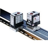
Isolation Amplifier
Manufacturer
EUROTHERM CONTROLS
Datasheet
1.1080-2000-1.pdf
(4 pages)
Specifications of 1090-2000-1
Width
2.85"
Output Accuracy
± 0.01%
Signal Input Type
Selectable Current Or Voltage
Configuration Setup
DIP Switch
Supply Voltage Max
240VAC
Iso-amp Mounting Type
DIN Rail
Display Alarm Type
2 Relay
Lead Free Status / RoHS Status
na


Dynamic Deadband
The input must remain beyond the setpoint
for 100 milliseconds, uninterrupted, to qualify
as a valid trip condition. Likewise, the input
must fall outside the deadband and remain
there for 100 milliseconds to return the alarm
to an untripped condition. This effectively
results in a “dynamic deadband” - based on
time - in addition to the normal deadband.
Options
U
P
C620 Factory calibration to input
Configuration
The factory presets models AP1080 and
AP1090 as follows:
Input
Output
Trip
Latching
Failsafe
Deadband
Power
For other I/O ranges, remove the four base
screws and case to access the configuration
switches.
Replace the cover before applying power.
Refer to Figure 4 for switch locations.
Input
1. Position input jumper “W2” for Current or
Voltage inputs.
Figure 1: Limit alarm operation and
effect of deadband.
Urethane coating of internal
circuitry for protection from
corrosive atmospheres.
Top Mounted, Ten-Turn Dial(s)
for setpoint adjustment.
range, setpoints and output
relays. Not available with
option P.
V
Current
I
AP1080
0-20mA
Single, DPDT Dual, SPDT
HI
No
Yes
0.25%
120VAC
Voltage
V
I
AP1090
0-20mA
A: HI, B: LO
No
No
120VAC
A/B: 0.25%
2. Set position 1 of the Mode Selector for
Unipolar or Bipolar operation. Unipolar is
the default.
Note: A bipolar span selection will double
any span from Table 1 (e.g., 10V unipolar
span = ±10V bipolar span)
3. Using Table 1, configure positions 1
through 4 of the Input Range Selector for the
desired maximum setpoint input. Round
desired maximum input values to the next
highest range (e.g., 0-120V = 200V range).
Output
Configure the Mode Selector for the required
function. See Figure 6.
Power
Configure the AC jumpers for either 120 or
240 VAC operation. See Figure 5.
Calibration
Note: To maximize thermal stability, final
calibration should be performed in the oper-
ating installation, allowing approximately 1-
2 hours for warmup and thermal equilibrium
of the system.
Setpoint: Set deadband at its minimum (fac-
tory default - 20 turns Counter Clockwise)
before adjusting the setpoint. With the
specified trip voltage or current input ap-
plied, adjust setpoint until the relay trips.
For HI trip calibration, start with the setpoint
above the desired trip. For LO trip calibra-
tion, start below the desired trip.
Deadband: Set deadband to its minimum
(factory default - fully CCW). Set setpoint
to desired trip. Adjust voltage/current input
until relay trips. Readjust deadband to 50%
(20 turns CW). Set voltage/current input to
desired deadband position. Slowly adjust
deadband until relay untrips.
Note that Custom Calibration (option C620)
is available from the factory (settings MUST
be within specifications):
a) Setpoint A: Type (HI/LO); Units (mA,
b) Setpoint B (1090 only): Type (HI/
c) Latching (ON/OFF)
d) Failsafe (ON/OFF)
ON
BP
mV, V); Deadband (%)
LO); Units (mA, mV, V); Deadband
(%)
1 2 3 4
Unipolar
5
6
ON
BP
1 2 3 4
Bipolar
5
6
*Note: Use Jumper (W2) to configure either voltage or
current input. All unipolar input ranges are zero based.
Note that if a deadband entry is not specified,
the default entry will be used.
Relay Protection and
EMI Suppression
When switching inductive loads, maximum
relay life and transient EMI suppression is
achieved using external protection (see Fig-
ures 2 & 3). Place all protection devices
directly across the load and minimize all lead
lengths. For AC inductive loads, place a prop-
erly-rated MOV across the load in parallel
with a series RC snubber. Use a 0.01 to 0.1 F
pulse film capacitor (foil polypropylene rec-
ommended) of sufficient voltage, and a 47 ,
1/2W carbon resistor. For DC inductive loads,
place a diode across the load (PRV > DC
supply, 1N4006 recommended) with (+) to
cathode and (-) to anode (the RC snubber is an
optional enhancement).
2000 Input Ranges
Related parts for 1090-2000-1
Image
Part Number
Description
Manufacturer
Datasheet
Request
R

Part Number:
Description:
TERMINAL WRAPOST BR-360 .510"
Manufacturer:
Mill-Max Manufacturing Corp.
Datasheet:
Part Number:
Description:
TERMINAL WRAPOST BR-360 .510"
Manufacturer:
Mill-Max Manufacturing Corp.
Datasheet:
Part Number:
Description:
TERMINAL WRAPOST BR-360 .510"
Manufacturer:
Mill-Max Manufacturing Corp.
Datasheet:
Part Number:
Description:
TERMINAL WRAPOST BR-360 .510"
Manufacturer:
Mill-Max Manufacturing Corp.
Datasheet:


Part Number:
Description:
26W 220V.- 12V.HAZ.LOC.FLOUR. 100CORD
Manufacturer:
DANIEL WOODHEAD
Part Number:
Description:
STANDARD WIRE WRAP PIN
Manufacturer:
Mill-Max Manufacturing Corp.

Part Number:
Description:
EUROTHERM CONTROLLER PART NUMBER 2416/P4/VH/M2/XX/FH/XX/ENG/XXXX/XXXXXX
Manufacturer:
EUROTHERM CONTROLS
Part Number:
Description:
EUROTHERM RESISTOR 2.49 OHM 0.1% FOR MODEL 2801I PROCESS INDICATOR
Manufacturer:
EUROTHERM CONTROLS

Part Number:
Description:
PID TEMPERATURE CONTROLLER
Manufacturer:
EUROTHERM CONTROLS
Datasheet:
Part Number:
Description:
Modbus Master Communications Module
Manufacturer:
EUROTHERM CONTROLS
Datasheet: