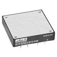
BCP-5/15-3.3/15-D24-C Murata Power Solutions Inc, BCP-5/15-3.3/15-D24-C Datasheet - Page 5

BCP-5/15-3.3/15-D24-C
Manufacturer Part Number
BCP-5/15-3.3/15-D24-C
Description
DC/DC Converter
Manufacturer
Murata Power Solutions Inc
Series
BCPr
Datasheet
1.BCP-515-3.315-D24-C.pdf
(14 pages)
Specifications of BCP-5/15-3.3/15-D24-C
Dc / Dc Converter O/p Type
Fixed
No. Of Outputs
2
Input Voltage
18V To 36V
Power Rating
50W
Output Voltage
5V
Output Current
15A
Output Voltage 2
3.3V
Output Current 2
15A
Supply Voltage
24V
Product
Isolated
Output Power
75 W
Input Voltage Range
18 V to 36 V
Input Voltage (nominal)
24 V
Number Of Outputs
2
Output Voltage (channel 1)
5 V
Output Current (channel 1)
15 A
Output Voltage (channel 2)
3.3 V
Output Current (channel 2)
15 A
Isolation Voltage
1.5 KV
Package / Case Size
Half Brick
Lead Free Status / RoHS Status
Lead free / RoHS Compliant
5V & 3.3V Outputs/Returns
The BCP Series outputs (pins 7 & 10) and returns (pins 6 & 9) are isolated
from the +V
transistors.
to the DC/DC converter. Though the returns are common within the DC/DC
converter, the regulating control loop for each output is sensed directly at its
respective output and return pins. In order to maintain optimum regulation if
ground plane is not used, it is critical that PC board layouts also return each
output to its corresponding return pin.
Filtering and Noise Reduction
All BCP DC/DC Converters achieve their rated ripple and noise specifi cations
using the external input and output capacitors specifi ed in the Performance/
Functional Specifi cations table. In critical applications, input/output noise may
be further reduced by installing additional external I/O caps. Input capacitors
should be selected for bulk capacitance, low ESR and high rms-ripple-current
ratings. Output capacitors should be selected for low ESR and appropriate
frequency response. All caps should have appropriate voltage ratings and be
mounted as close to the converters as possible.
of your particular load and layout conditions. Our Applications Engineers will
be pleased to recommend potential solutions and can discuss the possibility of
our modifying a device’s internal fi ltering to meet your specifi c requirements.
Contact our Applications Engineering Group for additional details.
Input Fusing
Certain applications and/or safety agencies may require the installation of fuses
at the inputs of power conversion components. Fuses should also be used if
the possibility of sustained, non-current-limited, input-voltage polarity reversals
exists. For BCP DC/DC Converters, you should use fast-blow type fuses with
values no greater than the following.
Fuses should be installed in the +Input line.
Input Overvoltage/Undervoltage Shutdown and Start-Up Threshold
Under normal start-up conditions, devices will not begin to regulate until the
ramping-up input voltage exceeds the Start-Up Threshold Voltage (35V for
"D48" models). Once operating, devices will not turn off until the input voltage
drops below the Undervoltage Shutdown limit (32V for "D48" models). Subse-
quent re-start will not occur until the input is brought back up to the Start-Up
Threshold. This built-in hysteresis prevents any unstable on/off situations from
occurring at a single voltage.
T E C H N I C A L N O T E S
The +5V Return (pin 6) and +3.3V Return (pin 9) are connected internal
The most effective combination of external I/O capacitors will be a function
"D24" Models
"D48" Models
V
IN
IN
and –V
Range
IN
inputs (pins 4 & 1) via a transformer and opto-coupled
Fuse Value
6 Amps
4 Amps
www.murata-ps.com
listed in the Performance/Functional Specifi cations will cause the device to
shutdown. A built-in hysteresis (2V typical for "D24" models, 4V typical for
"D48" models) will not allow the converter to restart until the input voltage is
suffi ciently reduced.
Start-Up Time
The V
ing input voltage crosses the turn-on threshold point and the fully-loaded
output voltage enters and remains within its specifi ed accuracy band. Actual
measured times will vary with input source impedance, external input capaci-
tance, and the slew rate and fi nal value of the input voltage as it appears to the
converter.
input voltage applied but is turned off via the On/Off Control. The specifi cation
defi nes the interval between the time at which the converter is turned on and
the fully loaded output voltage enters and remains within its specifi ed accuracy
band.
On/Off Control (Standard feature)
The On/Off Control (pin 3) may be used for remote on/off operation. As shown
in Figure 1A, the control pin is referenced to the –Input (pin 1) and will be
pulled to a high state internally. The standard BCP converter (no suffi x) is
designed so that it is enabled when the control pin is left open and disabled
when the control pin is pulled low (to less than +0.6V relative to –Input).
cal relay or an open-collector/open-drain drive circuit (optically isolated if
appropriate). The drive circuit should be able to sink approximately 1mA for
logic low.
disabled (pin 3 pulled low for no-suffi x models) while input power is ramping
up and then "released" once the input has stabilized.
On/Off Control pin ("N" suffi x added to part number), operation is opposite to
that described above. The converter is disabled when the On/Off Control pin is
left open and enabled when pulled low.
Input voltages exceeding the input overvoltage shutdown specifi cation
The On/Off to V
Dynamic control of the on/off function is best accomplished with a mechani-
The on/off control function is designed such that the converter can be
For BCP converters confi gured with the negative-polarity option on the
IN
to V
Dual Output, Mixed Voltage, Isolated 5V & 3.3 V,
OUT
Figure 1A. No Suffi x
start-up time is the interval between the time at which a ramp-
4
3
1
OUT
+INPUT
ON/OFF
CONTROL
–INPUT
start-up time assumes the converter has its nominal
21k
"Half-Brick" 75 W DC/DC Converters
3.3V
12 Nov 2009 MDC_BCP_75W.B03 Page 5 of 14
Figure 1B. "N" Suffi x
BCP Models
email: sales@murata-ps.com
4
3
1
+INPUT
ON/OFF
CONTROL
–INPUT
100k


