MPDTH03060WAS Murata Power Solutions Inc, MPDTH03060WAS Datasheet - Page 2
MPDTH03060WAS
Manufacturer Part Number
MPDTH03060WAS
Description
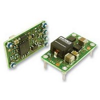
CONVERTER, DC/DC, POLA, 10A, 25W
Manufacturer
Murata Power Solutions Inc
Datasheet
1.MPDTH03060WAH.pdf
(6 pages)
Specifications of MPDTH03060WAS
Output Type
POLA
No. Of Output Channels
1
Input Voltage
3V To 3.6V
Power Rating
25W
Output Current
10A
Supply Voltage
3.3V
Dc / Dc Converter Case Style
SMD
Svhc
No SVHC (18-Jun-2010)
External
RoHS Compliant
Dc / Dc Converter O/p Type
POLA
No. Of Outputs
1
Rohs Compliant
Yes


Notes:
c All specifi cations are typical at nominal input line voltage, nominal output voltage and full load,
d "TH" is a pinned through-hole package. "SM" is a surface mount package.
e Vin=3.3V, Vout=2.5V, Iout=7A
f Vin=5V, Vout=3.3V, Iout=7A
MPDTH**060 Series Performance and Functional Specifi cations
All specifi cations are typical unless noted.
Specifi cation Notes:
(1) All specifi cations are typical unless noted. General conditions for Specifi cations are +25 deg.C
(2) An external output capacitor is not required. However, a 330
(3) The required input capacitor must have a ripple current rating of 500 mA RMS or greater for
SPECIFICATION SUMMARY AND ORDERING GUIDE c
MPDTH03060WAH
MPDTH03060WAS
MPDTH05060WAH
MPDTH05060WAS
MPDTH12060WAH
MPDTH12060WAS
www.murata-ps.com
Model Number
Input Voltage Range
Start-Up Voltage
Undervoltage Shutdown
External Input Capacitor
(See note 3)
Remote On/Off Inhibit Control
Tracking Input
Margin Controls
Minimum Loading
Nominal Accuracy
Voltage Adjustment Range
Temperature Coeffi cient
Ripple/Noise
Ta=+25 deg.C. unless otherwise noted. See detailed specifi cations.
ambient, Vin=nominal, Vout=+2.5V, full load. Cin=100
supplied for extended testing under power. For model MPDTH12060, the required input capaci-
tor is 560
transient response.
models MPDTH03060 and MPDTH05060. For model MPDTH12060, the ripple rating must be
1050 mA RMS or greater.
Tracking Input Range
Positive Logic
Current
Current when grounded
Slew rate
μ
F. See note 3.
(Volts)
0.8-2.5
0.8-2.5
0.8-3.6
0.8-3.6
1.2-5.5
1.2-5.5
Vout
Iout (Amps, Power
max.)
10
10
10
10
10
10
See Ordering Guide
2.45 Volts (MPDTH03060)
4.3 Volts (MPDTH05060)
9.5 Volts (MPDTH12060)
2.4 Volts (MPDTH03060)
3.7 Volts (MPDTH05060)
9.0 Volts (MPDTH12060)
330 μF, required (MPDTH03060 and
MPDTH05060)
560 μF required (MPDTH12060)
OFF = -0.2V to +0.5 V max. or ground pin
ON = open pin (internal pullup)
-130 μA [5]
-130 μA
1 Volt per mSec max.
-0.3V to (+Vin + 0.3V)
-5% or +5% adjustment of Vout when the
respective margin control is grounded. Current,
-8 μA sink.
No minimum load
±2 % max. of Vsetting
See Ordering Guide
±40 ppm. per °C. of Vout
See Ordering Guide
Output
Input
Output
(Watts)
25
25
36
36
55
55
μ
F, Cout= 0
μ
Ripple&Noise
F output capacitor improves
(mV pk-pk)
25(6)
25(6)
25(7)
25(7)
33(8)
33(8)
μ
F. Adequate airfl ow must be
±1.25% ±1.5%
±1.25% ±1.5%
±1.25% ±1.5%
±1.25% ±1.5%
±1.25% ±1.5%
±1.25% ±1.5%
Line
Regulation
Load
g Vin=12V, Vout=5V, Iout=8A
h Vin=3.3V, Vout=2V, Iout=10A
i Vin=5V, Vout=3.3V, Iout=10A
j Vin=12V, Vout=3.3V, Iout=10A
k The minimum input voltage is +2.95V. Or (Vout + 0.65V.), whichever is greater.
l RoHS6 compliance does not claim EU RoHS exemption 7b (lead in solder).
Vin nom.
(Volts)
(4) Mean Time Before Failure is calculated using the Telcordia (Belcore) TR-332 50% stress, ground
(5) Track input is grounded or equal to Vin.
(6) There is no input protection against overvoltage or reversed polarity. Please provide proper
(7) The outputs are not intended to sink appreciable reverse current.
(8) Output current limit and short circuit protection is non-latching. When the overcurrent fault is
12.0
12.0
3.3
3.3
5.0
5.0
Line/Load Regulation
Effi ciency
Maximum Capacitive Loading
Current Limit Inception
Short Circuit Mode
Sequencing
VoSense Input
Dynamic Load Response
Switching Frequency
Calculated MTBF [4]
Operating Temperature Range
Storage Temperature Range
Cap-ESR>=0.004 Ohms
Cap-ESR <0.004 Ohms
Protection Method
Short Circuit Duration
benign conditions, Tambient=+40 deg.C.
fusing and a back-biased diode if there is the possibility of improper polarity. Refer to the Con-
nection Diagram.
removed, the converter will immediately recover.
Input (9)
10.8-13.2
10.8-13.2
4.5-5.5
4.5-5.5
Range
(Volts)
3-3.6
3-3.6
Technical enquiries email: sales@murata-ps.com, tel:
Effi ciency
93(3)
93(3)
94(4)
94(4)
94(5)
94(5)
(%)
MPDTH***60 Series
Dynamic Characteristics
Adjustable Non-isolated 10-Amp
Environmental
0.995x0.62x0.35
0.995x0.62x0.38 25.27x15.75x9.57
0.995x0.62x0.35
0.995x0.62x0.38 25.27x15.75x9.57
0.995x0.62x0.35
0.995x0.62x0.38 25.27x15.75x9.57
Case(inches)
See Ordering Guide
See Ordering Guide
5,500 μF non-ceramic [2]
300 μF ceramic
20 Amps
Autorecovery after overload removal
Continuous, no damage (output shorted to
ground)
Start-up of multiple units may be synchronized
by connecting tracking pins.
Connect Sense to Vout remotely at the load for
optimal accuracy. If not used at the load, con-
nect VoSense to Vout at the converter.
70 μSec to within ±2% of fi nal value (50 to
100% load step, 1A/μSec load step, 330 μF
external output cap)
300 KHz (MPDTH03060 and MPDTH05060)
350 KHz (MPDTH12060)
6 million hours,min. (MPDTH03060 and
MPDTH03060)
5.9 million hours,min. (MPDTH12060)
-40 to +85 deg.C.
-40 to +125 deg.C.
POLA DC/DC Converters
MPDTH_60 Series.A07 Page 2 of 6
Package
25.27x15.75x9.0
25.27x15.75x9.0
25.27x15.75x9.0
Case(mm)
+1 508 339 3000
Type(2)
SM
SM
SM
TH
TH
TH
Related parts for MPDTH03060WAS
Image
Part Number
Description
Manufacturer
Datasheet
Request
R

Part Number:
Description:
POWER OVER ETHERNET MODULE
Manufacturer:
Murata Power Solutions Inc
Datasheet:

Part Number:
Description:
POWER OVER ETHERNET MODULE
Manufacturer:
Murata Power Solutions Inc
Datasheet:

Part Number:
Description:
POWER OVER ETHERNET MODULE
Manufacturer:
Murata Power Solutions Inc
Datasheet:

Part Number:
Description:
POWER OVER ETHERNET MODULE
Manufacturer:
Murata Power Solutions Inc
Datasheet:

Part Number:
Description:
Power Inductors 2.2mH1.4A
Manufacturer:
Murata Power Solutions Inc
Datasheet:

Part Number:
Description:
Power Inductors 6.8uH 3.6A 20mOhm Toroidal SMT
Manufacturer:
Murata Power Solutions Inc
Datasheet:

Part Number:
Description:
Power Inductors Radial1.5mH 150mA
Manufacturer:
Murata Power Solutions Inc
Datasheet:
Part Number:
Description:
Power Inductors 680uH 2.2A 1.3MHz Radial PCB Mounting
Manufacturer:
Murata Power Solutions Inc
Datasheet:
Part Number:
Description:
Power Inductors 6.8mH0.5A
Manufacturer:
Murata Power Solutions Inc
Datasheet:
Part Number:
Description:
Power Inductors 470uH2.7A
Manufacturer:
Murata Power Solutions Inc
Datasheet:

Part Number:
Description:
Transformers 5Vin 5Vout 200mA 4000Vdc 1:1.33 turn
Manufacturer:
Murata Power Solutions Inc
Datasheet:

Part Number:
Description:
POWER SUPPLY
Manufacturer:
Murata Power Solutions Inc
Datasheet:

Part Number:
Description:
DPM LED MINI 2VDC 3.5DIG LP RED
Manufacturer:
Murata Power Solutions Inc
Datasheet:

Part Number:
Description:
CONV DC/DC 1W 5VIN 5VOUT SIP SGL
Manufacturer:
Murata Power Solutions Inc
Datasheet:

Part Number:
Description:
CONV DC/DC 1W 5VIN 3.3V SIP SGL
Manufacturer:
Murata Power Solutions Inc
Datasheet: