MPDTH03060WAS Murata Power Solutions Inc, MPDTH03060WAS Datasheet - Page 6
MPDTH03060WAS
Manufacturer Part Number
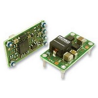
MPDTH03060WAS
Description
CONVERTER, DC/DC, POLA, 10A, 25W
Manufacturer
Murata Power Solutions Inc
Datasheet
1.MPDTH03060WAH.pdf
(6 pages)
Specifications of MPDTH03060WAS
Output Type
POLA
No. Of Output Channels
1
Input Voltage
3V To 3.6V
Power Rating
25W
Output Current
10A
Supply Voltage
3.3V
Dc / Dc Converter Case Style
SMD
Svhc
No SVHC (18-Jun-2010)
External
RoHS Compliant
Dc / Dc Converter O/p Type
POLA
No. Of Outputs
1
Rohs Compliant
Yes


Murata Power Solutions, Inc.
11 Cabot Boulevard, Mansfi eld, MA 02048-1151 U.S.A.
Tel: (508) 339-3000 (800) 233-2765 Fax: (508) 339-6356
www.murata-ps.com email: sales@murata-ps.com ISO 9001 and 14001 REGISTERED
Murata Power Solutions, Inc. makes no representation that the use of its products in the circuits described herein, or the use of other
technical information contained herein, will not infringe upon existing or future patent rights. The descriptions contained herein do not imply
the granting of licenses to make, use, or sell equipment constructed in accordance therewith. Specifi cations are subject to change without
notice.
Tracking Input
When enabled, the tracking function allows the output to follow an external
analog signal presented at the Tracking input. This pin becomes active
approximately 50 mS after the input voltage has been applied and the con-
verter reaches regulation. External track inputs must be referred to Ground.
Several converters may be Tracked in parallel to generate outputs which rise
and fall together.
The Tracking input range is zero Volts up to the nominal set-point output
voltage. If the Tracking input rises above the Vout nominal voltage, Vout will
remain at the set point after the power up ramp. If Track is unused, it should
be connected to +Vin.
Please note that because of the Under Voltage input lockout feature (UVLO),
the output cannot follow Track In during power up.
Over-Current Output Protection
If excess current is drawn from the converter, the output will shut down
and then periodically attempt to restart with narrow full power cycles. If the
excess load is reduced to within the rated maximum load, the converter
will immediately restart and operate normally. If the load is still too great,
another power-down cycle will begin. This is called “hiccup” operation. It
signifi cantly reduces the output power to avoid damage. The converter will
quickly and automatically recover once the load is reduced.
Pre-Bias Operation
The MPDTHxx060 series of converters use synchronous rectifi cation in
their output circuits. Normally, synchronous rectifi cation may cause excess
current being sunk back in to the converter if there is higher external output
voltage present. If such prebias voltage is present on the output at the time
of startup, the converter will operate in a manner which avoids excessive
reverse current being sunk back into the output. This pre-bias protection
will continue until the converter achieves normal regulation at its set-point
output voltage.
In order to achieve successful pre-bias voltage protection, several conditions
must be met:
[1] The pre-bias voltage must be lower than the expected fi nal set-point
output voltage. If the pre-bias voltage remains higher than the set-point
www.murata-ps.com
APPLICATION NOTES
© 2009 Murata Power Solutions, Inc.
03/27/09
and is capable of back-driving excess current, possible output damage may
occur. If the pre-bias voltage has high impedance or has very limited current
capability, normal startup will proceed.
[2] Tracking operation must not be used during pre-bias startup. The Track-
ing input should be either open or connected to Vin so that normal soft start
will proceed. After successful startup of approximately 50 mSec, Tracking
may be resumed.
[3] Carefully examine any output circuits with large external output capaci-
tors and low-ESR. If there is no bleeder circuit or other method to reduce the
stored voltage AND the cap voltage is higher than the expected set-point,
operation may fail or the output may be damaged. Smaller capacitors with
lower energy storage should not interfere with startup. See the recom-
mended Connection Diagram. Use only as much output capacitance as
needed.
Also be careful immediately turning the converter back on after the Inhibit
control turns the converter off. Any energy stored in larger output capacitors
may cause the problems described above.
Margin Up/Down Controls
Ground each Margin control to increase or decrease the output voltage by
±5% from its setpoint value. If not needed, leave the margin controls uncon-
nected (open).
The margin controls are analog inputs and are not logic compatible. If a
switch is not used to ground, a small signal transistor (such as an n-channel
MOSFET with low off-state leakage) will work if biased fully into either pin-
choff/cutoff or saturation. Sink current is approximately -8 μA when ON and
the open circuit voltage is approximately 0.8 Volts when OFF. Do not ground
both margin controls simultaneously.
For output changes less than ±5%, insert an additional resistor in series
with the switch or transistor to ground. The margin adjustment equation is:
R-up or R-down (in KΩ) = (499 / delta%) – 99.8
Where “delta%” is the desired change in percent of Vout up or down relative
to the set-point output. Be sure to use low tempco precision resistors.
USA:
Canada:
UK:
France:
Germany:
Japan:
China:
Singapore:
Mansfi eld (MA), Tel: (508) 339-3000, email: sales@murata-ps.com
Toronto, Tel: (866) 740-1232, email: toronto@murata-ps.com
Milton Keynes, Tel: +44 (0)1908 615232, email: mk@murata-ps.com
Montigny Le Bretonneux, Tel: +33 (0)1 34 60 01 01, email: france@murata-ps.com
München, Tel: +49 (0)89-544334-0, email: munich@murata-ps.com
Tokyo, Tel: 3-3779-1031, email: sales_tokyo@murata-ps.com
Osaka, Tel: 6-6354-2025, email: sales_osaka@murata-ps.com
Shanghai, Tel: +86 215 027 3678, email: shanghai@murata-ps.com
Guangzhou, Tel: +86 208 221 8066, email: guangzhou@murata-ps.com
Parkway Centre, Tel: +65 6348 9096, email: singapore@murata-ps.com
Technical enquiries email: sales@murata-ps.com, tel:
MPDTH***60 Series
Adjustable Non-isolated 10-Amp
POLA DC/DC Converters
MPDTH_60 Series.A07 Page 6 of 6
+1 508 339 3000
Related parts for MPDTH03060WAS
Image
Part Number
Description
Manufacturer
Datasheet
Request
R

Part Number:
Description:
POWER OVER ETHERNET MODULE
Manufacturer:
Murata Power Solutions Inc
Datasheet:

Part Number:
Description:
POWER OVER ETHERNET MODULE
Manufacturer:
Murata Power Solutions Inc
Datasheet:

Part Number:
Description:
POWER OVER ETHERNET MODULE
Manufacturer:
Murata Power Solutions Inc
Datasheet:

Part Number:
Description:
POWER OVER ETHERNET MODULE
Manufacturer:
Murata Power Solutions Inc
Datasheet:

Part Number:
Description:
Power Inductors 2.2mH1.4A
Manufacturer:
Murata Power Solutions Inc
Datasheet:

Part Number:
Description:
Power Inductors 6.8uH 3.6A 20mOhm Toroidal SMT
Manufacturer:
Murata Power Solutions Inc
Datasheet:

Part Number:
Description:
Power Inductors Radial1.5mH 150mA
Manufacturer:
Murata Power Solutions Inc
Datasheet:
Part Number:
Description:
Power Inductors 680uH 2.2A 1.3MHz Radial PCB Mounting
Manufacturer:
Murata Power Solutions Inc
Datasheet:
Part Number:
Description:
Power Inductors 6.8mH0.5A
Manufacturer:
Murata Power Solutions Inc
Datasheet:
Part Number:
Description:
Power Inductors 470uH2.7A
Manufacturer:
Murata Power Solutions Inc
Datasheet:

Part Number:
Description:
Transformers 5Vin 5Vout 200mA 4000Vdc 1:1.33 turn
Manufacturer:
Murata Power Solutions Inc
Datasheet:

Part Number:
Description:
POWER SUPPLY
Manufacturer:
Murata Power Solutions Inc
Datasheet:

Part Number:
Description:
DPM LED MINI 2VDC 3.5DIG LP RED
Manufacturer:
Murata Power Solutions Inc
Datasheet:

Part Number:
Description:
CONV DC/DC 1W 5VIN 5VOUT SIP SGL
Manufacturer:
Murata Power Solutions Inc
Datasheet:

Part Number:
Description:
CONV DC/DC 1W 5VIN 3.3V SIP SGL
Manufacturer:
Murata Power Solutions Inc
Datasheet: