LSN2-T/22-D12NG-C Murata Power Solutions Inc, LSN2-T/22-D12NG-C Datasheet - Page 3
LSN2-T/22-D12NG-C
Manufacturer Part Number
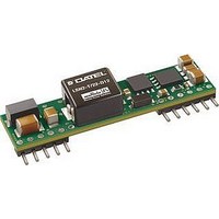
LSN2-T/22-D12NG-C
Description
DC/DC Converter
Manufacturer
Murata Power Solutions Inc
Series
LSN2r
Specifications of LSN2-T/22-D12NG-C
No. Of Outputs
1
Input Voltage
8.3V To 14V
Power Rating
112W
Output Current
22A
Approval Bodies
UL, CSA
Supply Voltage
14VDC
Dc / Dc Converter Case Style
SIP
Dc/dc Converter Mounting
Through Hole
Product
Non-Isolated / POL
Output Power
110 W
Input Voltage Range
8.3 V to 14 V
Input Voltage (nominal)
12 V
Number Of Outputs
1
Output Voltage (channel 1)
0.8 V to 5 V
Output Current (channel 1)
22 A
Package / Case Size
SIP
Output Type
Low Voltage Selectable
Output Voltage
0.8 V to 5 V
Lead Free Status / RoHS Status
Lead free / RoHS Compliant


Performance/Functional Specifi cations
INPUT
OUTPUT
Input Voltage Range
Isolation
Start-Up Threshold
Undervoltage Shutdown
Overvoltage Shutdown
Refl ected (Back) Ripple Current
Internal Input Filter Type
Reverse Polarity Protection
Recommended External Fuse
Input Current:
Remote On/Off Control:
Voltage Output Range
Minimum Loading
Accuracy (50% load)
Voltage Adjustment Range
Temperature Coeffi cient
Ripple/Noise (20 MHz bandwidth)
Line/Load Regulation (See Tech Notes)
Effi ciency
Maximum Capacitive Loading:
Current Limit Inception: (98% of V
Short Circuit Mode
Short Circuit Duration
Prebias Startup
Remote Sense to V
Power Good Output
Sequencing (Omit “B” model suffi x)
Full Load Conditions
Inrush Transient
Shutdown Mode (Off, UV, OT)
Output Short Circuit
Cap-ESR = 0.001 to 0.01:
No Load
Low Line (V
Positive Logic (no model suffi x)
Negative Logic (“N” model suffi x)
Current
Cap-ESR >0.01:
Short Circuit Current Output
Protection Method
Slew Rate
Startup delay until sequence start
Tracking accuracy, rising input
Tracking accuracy, falling input
Sequence pin input impedance
(“G” suffi x)
Power_Good Confi guration
IN
= V
(16)
MIN
OUT
(6)
(17)
(14)
)
(5)
(13)
(15)
(2)
OUT
)
See Ordering Guide
Not isolated, input and output commons
are internally connected
8.1 Volts
7.5 Volts
None
20mAp-p
Capacitive
See fuse information
25 Amps
See Ordering Guide
0.4A
5mA
60mA
100mA, 5V
12.62 Amps
OFF = ground pin to +0.3V max.
ON = open pin or +2.5V min. to +V
ON = 0 to +0.3V max.
OFF = open pin or +2.5V min. to +V
1mA max.
See Ordering Guide
No minimum load
±2% of V
See Ordering Guide
±0.02% of V
See Ordering Guide and
See Ordering Guide and
See Ordering Guide
2000μF
10,000μF
45 Amps (cold startup)
43 Amps (after warm up)
600mA
Hiccup autorecovery on overload removal
Continuous, no damage (output shorted
to ground)
Converter will start up if the external
output voltage is less than V
2V max. per millisecond
10 milliseconds
V
V
1M:
0.5V max.
TRUE (OK) = open drain
FALSE (not OK) = Signal Ground to 0.4V
MOSFET to ground with external user
pullup, 10mA max. sink
OUT
OUT
2
= ±200mV max. of Sequence In
= ±400mV max. of Sequence In
sec
(1)
NOM
(7)
OUT
OUT
range per °C
(8)
(10)
SET
www.murata-ps.com
IN
IN
max.
max.
Performance/Functional Specifi cation Notes:
(1)
(2)
(3)
(4)
(5)
(6)
DYNAMIC CHARACTERISTICS
ENVIRONMENTAL
PHYSICAL
Dynamic Load Response
Start-Up Time
Switching Frequency
Calculated MTBF
Operating Temperature Range
See Derating Curves
Operating PC Board Temperature
Storage Temperature Range
Thermal Protection/Shutdown
Relative Humidity
Outline Dimensions
Weight
Pin Material
Electromagnetic Interference
Safety
Flammability Rating
ABSOLUTE MAXIMUM RATINGS
Input Voltage (Continuous or transient)
On/Off Control
Input Reverse Polarity Protection
Output Current
Storage Temperature
Lead Temperature (soldering 10 sec. max.) +280°C
These are stress ratings. Exposure of devices to any of these conditions may adversely affect
long-term reliability. Proper operation under conditions other than those listed in the Perfor-
mance/Functional Specifi cations Table is not implied.
All models are tested and specifi ed with external 1 || 10μF ceramic/tantalum output capacitors
and a 22μF external input capacitor. All capacitors are low ESR types. These capacitors are
necessary to accommodate our test equipment and may not be required to achieve specifi ed
performance in your applications. All models are stable and regulate within spec under no-load
conditions.
General conditions for Specifi cations are +25°C, V
nal” output voltage is +5V.
Input Back Ripple Current is tested and specifi ed over a 5-20MHz bandwidth. Input fi ltering is
C
Note that Maximum Power Derating curves indicate an average current at nominal input voltage.
At higher temperatures and/or lower airfl ow, the DC/DC converter will tolerate brief full current
outputs if the total RMS current over time does not exceed the derating curve.
Mean Time Before Failure is calculated using the Telcordia (Belcore) SR-332 Method 1, Case 3,
ground fi xed conditions, T
The On/Off Control may be driven with external logic or by applying appropriate external voltages
which are referenced to –Input Common. The On/Off Control Input should use either an open
collector/open drain transistor or logic gate which does not exceed +V
resistor to +V
Short circuit shutdown begins when the output voltage under increasing load degrades approxi-
mately 2% from the selected setting.
IN
(50-100-50% load step, di/dt = 20A/μsec)
(V
(conducted and radiated)
= 2 x 100μF tantalum, C
IN
on to V
IN
OUT
will cause the “ON” state for negative logic models.
(7)
regulated or On/Off to V
22A Selectable-Output DC/DC Converters
(4)
PCBOARD
BUS
25 Jun 2010
= 1000μF electrolytic, L
= +25°C, full output load, natural air convection.
OUT
LSN2-T/22-D12
MDC_LSN2-T/22-D12_B03Δ
)
40μsec to ±2% of fi nal value
7msec for V
250 ±30kHz
TBC Hours
–40 to +85°C with derating
–40 to +100°C max.
–55 to +125°C
+115°C
To 85°C/85% RH, non-condensing
See Mechanical Specifi cations
0.28 ounces (7.8 grams)
Tin plate over copper alloy
FCC part 15, class B, EN55022 (may
need external fi lter)
UL/cUL 60950-1 CSA-C22.2 No.60950-1
IEC/EN 60950-1
UL94V-0
+15 Volts
–0V min. to +V
See Fuse section
Current-limited. Devices can
withstand sustained short circuit
without damage.
–55 to +125°C
IN
Non-isolated, DOSA-SIP,
= nominal, V
BUS
= 1μH.
email: sales@murata-ps.com
OUT
OUT
= nominal
IN
= nominal, full load. “Nomi-
max.
IN
. A 68K: external pullup
(12)
Page 3 of 13
Related parts for LSN2-T/22-D12NG-C
Image
Part Number
Description
Manufacturer
Datasheet
Request
R

Part Number:
Description:
DC/DC Converters & Regulators 12Vin 0.8-5Vout 22A 112W NonIso DOSA-SIP
Manufacturer:
Murata Power Solutions Inc
Datasheet:
Part Number:
Description:
DC/DC Converters & Regulators 12Vin 0.8-5Vout 22A 112W Neg polarity
Manufacturer:
Murata Power Solutions Inc
Datasheet:

Part Number:
Description:
DC/DC Converter
Manufacturer:
Murata Power Solutions Inc
Datasheet:

Part Number:
Description:
DC/DC Converters & Regulators 12Vin 0.8-5Vout 30A 150W Power Good Out
Manufacturer:
Murata Power Solutions Inc
Datasheet:
Part Number:
Description:
DC/DC Converters & Regulators 12Vin 0.8-5Vout 30A 150W Neg polarity
Manufacturer:
Murata Power Solutions Inc
Part Number:
Description:
DC/DC Converters & Regulators 12Vin 0.8-5Vout 30A 150W PowerGood NegPl
Manufacturer:
Murata Power Solutions Inc

Part Number:
Description:
CONV DC/DC 30W 6A 0.75-5V SIP
Manufacturer:
Murata Power Solutions Inc
Datasheet:

Part Number:
Description:
CONV DC/DC 33W 10A .75-3.3V SIP
Manufacturer:
Murata Power Solutions Inc
Datasheet:

Part Number:
Description:
CONV DC/DC 50W 10A 0.75-5V SIP
Manufacturer:
Murata Power Solutions Inc
Datasheet:

Part Number:
Description:
CONV DC/DC 19.8W 6A .75-3.3V SIP
Manufacturer:
Murata Power Solutions Inc
Datasheet:

Part Number:
Description:
Transformers 5Vin 5Vout 200mA 4000Vdc 1:1.33 turn
Manufacturer:
Murata Power Solutions Inc
Datasheet:

Part Number:
Description:
POWER SUPPLY
Manufacturer:
Murata Power Solutions Inc
Datasheet:

Part Number:
Description:
DPM LED MINI 2VDC 3.5DIG LP RED
Manufacturer:
Murata Power Solutions Inc
Datasheet:

Part Number:
Description:
CONV DC/DC 1W 5VIN 5VOUT SIP SGL
Manufacturer:
Murata Power Solutions Inc
Datasheet:

Part Number:
Description:
CONV DC/DC 1W 5VIN 3.3V SIP SGL
Manufacturer:
Murata Power Solutions Inc
Datasheet: