8340-F410-P1M2-A2H0-5A ETA, 8340-F410-P1M2-A2H0-5A Datasheet

CIRCUIT BREAKER, HYDROMAGNETIC, 5A

8340-F410-P1M2-A2H0-5A

Manufacturer Part Number
8340-F410-P1M2-A2H0-5A
Description
CIRCUIT BREAKER, HYDROMAGNETIC, 5A
Manufacturer
ETA

Specifications of 8340-F410-P1M2-A2H0-5A

No. Of Poles
1
Fuse Current
5A
Interrupting Capacity
2000A
Approval Bodies
BUREAU VERITAS, CSA, EN60934, LLOYDS, QPL, UL, VDE
Breaking Capacity Current Ac
3500A
Breaking Capacity Current
RoHS Compliant
Current Rating
5A
Svhc
No SVHC (15-Dec-2010)
Rohs Compliant
Yes
Single, two and three pole magnetic circuit breakers with trip-free
mechanism and push/pull on/off manual actuation. A choice of fast
magnetic only or hydraulically delayed switching characteristics (Stype
MO or HM CBE to EN 60934) ensures suitability for a wide range of
applications. Convenient threadneck panel or plug-in mounting, and
with a white push button indicator band showing clearly the tripped/off
position. Available with auxiliary contacts (1 x N/O, 1 x N/C) for status
signalling and fitted with an unprotected shunt tap terminal as standard.
Approved to CBE standard EN 60934 (IEC 60934).
Control equipment, communications systems, power semiconductors.
Current
rating (A)
0.02
0.05
0.08
0.1
0.15
0.2
0.3
0.5
0.75
1
1.25
1.5
1.75
2
2.5
3
4
5
6
8
10
12
15
16
20
25
30
40
50
* 50 % ON duty / 60 min.
Authority
VDE (EN 60934)
UL 1077, CSA
UL 489 A
BV
CCC
05/06
Description
Typical application
Standard current ratings and typical internal resistance values
Approvals
(020505)
Voltage ratings
3 AC 415 V, AC 240 V, DC 80 V
DC 80 V
DC 80 V
3 AC 250 V; AC 250 V
DC 80 V
AC 250 V, DC 65 V
3 AC 415 V, AC 240 V, DC 80 V
DC 80 V
Magnetic and Hydraulic-Magnetic Circuit Breaker 8340-G2...
Internal resistance (Ω) per pole
curve
-F4/F5
583
94
35.8
23
9.9
5
2.44
0.79
0.39
0.25
0.15
0.10
0.083
0.059
0.044
0.028
< 0.02
å< 0.02
< 0.02
< 0.02
< 0.02
< 0.02
< 0.02
< 0.02
< 0.02
< 0.02*
< 0.02*
curves
-E1/H1/R1
2441
376
148
94
39
23
9.9
3.16
1.55
0.79
0.58
0.37
0.30
0.20
0.146
0.10
0.059
0.040
0.026
< 0.02
< 0.02
< 0.02
< 0.02
< 0.02
< 0.02
< 0.02
< 0.02
< 0.02
< 0.02
Current ratings
0.02...30 A
0.02...50 A 1 pole
0.02...50 A 1, 2 pole
0.02...30 A
0.05...30 A 1, 2 pole
0.1...30 A
0.02...30 A
0.02...50 A 1, 2 pole
0.56
0.29
curves
-E2/H2/R2
2449
365
144
84
38
22.4
9.7
3.1
1.51
0.77
0.36
0.24
0.138
0.099
0.057
0.038
0.026
< 0.02
< 0.02
< 0.02
< 0.02
< 0.02
< 0.02
< 0.02
< 0.02
1,2,3 pole
www.e-t-a.com
For further details please see chapter: Technical Information
Voltage rating
Current ratings
Auxiliary circuit
Typical life
Ambient temperature
Insulation co-ordination
(IEC 60664 and 60664A)
Dielectric strength
(IEC 60664 and 60664A)
Insulation resistance
Interrupting capacity I
Interrupting capacity
(UL 1077)
Interrupting capacity
(UL 489A)
Degree of protection
(IEC 60529/DIN 40050)
Vibration
Shock
Corrosion
Humidity
Mass
Technical data
operating area
3 AC 415 V,
AC 240 V:
DC 80 V:
pole to pole (2 + 3 pole) AC 1,500 V
main to auxiliary circuit AC 1,500 V
aux. circuit 11-12/23-24 AC 1,000 V
switching to trip circuit (-X) AC 1,500 V
with button down:
other mounting planes: 10 g (57-2000 Hz) at I
1 pole
0.02...30 A 6,000 operations at 1 x I
0.02...25 A 6,000 operations at 1 x I
0.02...30 A 10,000 operations at 1 x I
40 + 50 A 5,000 operations at 1 x I
AC:
DC:
cn
8340-G2...
3 AC 415 V; AC 240 V, 50/60 Hz; DC 80 V
0.02...50 A single pole (40+50 A DC only)
0.02...30 A multipole
1 A, AC 240 V/DC 65 V;
0.5 A, DC 80 V
10,000 operations at 1xI
rated impulse
withstand voltage
2.5 kV
reinforced insulation in operating area
test voltage
AC 3,000 V
1,200 A at AC; 2,000 A at DC
I
1 pole
2 pole
3 pole
1 pole
2 pole
2000 A
operating area IP40
terminal area IP00
10 g (57-2000 Hz), ±0.76 mm (10-57 Hz)
at 0.9 x I
to IEC 60068-2-6, test Fc
10 frequency cycles/axis
100 g (11 ms) at 1xI
100 g (11 ms) at 0.8 x I
to IEC 60068-2-27, test Ea
96 hours at 5 % salt mist,
to IEC 60068-2-11, test Ka
240 hours at 95 % RH
to IEC 60068-2-3, test Ca
approx. 70 g per pole
-40...+85 °C (-40...+185 °F)
> 100 MΩ (DC 500 V)
N
0.02...20 A
AC 250 V/3,500A
AC 250 V/3,500A
3AC 250V/3,500A 3AC250V/5,000A
0.02...50 A
0.02...30 A
N
2 pole
N
, directions 1,2,3,4,5
N
pollution
degree
2
N
N
N
N
N
, direction 6
, resistive
25...30 A
AC 250 V/3,500A
AC 250 V/5,000A
DC 80 V/3,500 A
DC 80 V/3500 A
, inductive
, inductive
N
, resistive
, resistive
3

Related parts for 8340-F410-P1M2-A2H0-5A

8340-F410-P1M2-A2H0-5A Summary of contents

Page 1

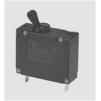
... Magnetic and Hydraulic-Magnetic Circuit Breaker 8340-G2... Description Single, two and three pole magnetic circuit breakers with trip-free mechanism and push/pull on/off manual actuation. A choice of fast magnetic only or hydraulically delayed switching characteristics (Stype CBE to EN 60934) ensures suitability for a wide range of applications. Convenient threadneck panel or plug-in mounting, and with a white push button indicator band showing clearly the tripped/off position ...

Page 2

... Magnetic and Hydraulic-Magnetic Circuit Breaker 8340-G2... Ordering information Type No. 8340 Magnetic push/pull circuit breaker Mounting G threadneck panel mounting Threadneck design 2 M12x1 Number of poles (main current paths) 0 single pole, switch only 1 single pole, protected 2 two pole, protected 3 three pole, protected 5 two pole, protected on one pole only ...

Page 3

... Magnetic and Hydraulic-Magnetic Circuit Breaker 8340-G2... Dimensions (2 pole) Dimensions (3 pole) 38 1.50 unit 1 unit 1 unit 2 unit 2 Cut-out dimensions: min. 40 min. 1.57 2 pole min. 60 min. 2.36 3 pole Installation drawings Terminal design - Terminal design - operating area mounting terminal area (reinforced insulation) area 29 1. .079 ...

Page 4

... Magnetic and Hydraulic-Magnetic Circuit Breaker 8340-G2... Curve F4 for DC, magnetic (undelayed) (I >20 A, 50% ON period, 60 min.) at +23 °C / +73.4 °F N 10000 1000 100 10 1 0.1 0.01 0.001 … times rated current Short delay curves E1 for DC and E2 for AC 50/60 Hz, hydraulic-magnetic 3 10000 1000 100 10 1 0.1 ...

Page 5

... Magnetic and Hydraulic-Magnetic Circuit Breaker 8340-G2... Socket Polarized socket with 18-P10-Si adapter 18-P10-Si-20025 (for ratings >16 A please contact E-T-A) retaining clip blade terminal A6.3-0.8 (QC .250) (accessory) to DIN 46244 polarized to ensure correct connection .394 in. .394 depth 19 80 .748 3.15 top-hat rail EN 50022-35x7.5 ...

Related keywords