8340-F410-P1M2-A2H0-5A ETA, 8340-F410-P1M2-A2H0-5A Datasheet - Page 2
8340-F410-P1M2-A2H0-5A
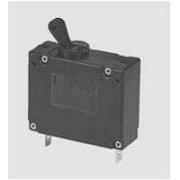
Manufacturer Part Number
8340-F410-P1M2-A2H0-5A
Description
CIRCUIT BREAKER, HYDROMAGNETIC, 5A
Manufacturer
ETA
Datasheet
1.8340-F410-P1M2-A2H0-10A.pdf
(5 pages)
Specifications of 8340-F410-P1M2-A2H0-5A
No. Of Poles
1
Fuse Current
5A
Interrupting Capacity
2000A
Approval Bodies
BUREAU VERITAS, CSA, EN60934, LLOYDS, QPL, UL, VDE
Breaking Capacity Current Ac
3500A
Breaking Capacity Current
RoHS Compliant
Current Rating
5A
Svhc
No SVHC (15-Dec-2010)
Rohs Compliant
Yes


3
Type No.
8340
8340 - G 2 1
*M4 thread recommended for I
M5 thread for I
Ordering information
Magnetic push/pull circuit breaker
Mounting
G
threadneck panel mounting
Threadneck design
2
M12x1
Number of poles (main current paths)
0
1
2
3
5
N
> 40 A
single pole, switch only
single pole, protected
two pole, protected
three pole, protected
two pole, protected on one pole only
Panel hardware
0
1
1 - N1 F4 - A 4 H1 1 1 - 8 A - U
without panel hardware
with hex nut M12x1 and washer 12/15
Terminal design
P1
N1
G3
G4
K3
K4
R1
X1
Magnetic and Hydraulic-Magnetic Circuit Breaker 8340-G2...
blade terminals A6.3-0.8mm (QC.250)
blade terminals A6.3-0.8mm (QC.250) with -A3
terminal (blade terminal) A6.3-0.8mm (QC.250)
screw terminals M4*
screw terminals M5*
screw terminals M4*
screw terminals M5*
round connectors ø6
blade terminals A6.3-0.8mm (QC.250),
separate switching and trip circuit
Characteristic curve
F4
F5
E1
E2
H1
H2
R1
R2
instantaneous trip: magn. 1.5-2.2xI
magn.1.2-1.7xI
short delay: magn.-hydr. 1.01-1.4 I
short delay: magn.-hydr. 1.01-1.4 I
medium delay: magn.-hydr. 1.01-1.4 I
medium delay: magn.-hydr. 1.01-1.4 I
long delay: magn.-hydr. 1.01-1.5 I
long delay: magn.-hydr 1.01-1.5 I
Actuator colour
A
N
> 20 A
black with white trip indicator band
Actuator marking
0
4
7
without marking
rated current
(legible with location pin above) standard
rated current
(legible with location pin below)
Auxiliary contacts
H0
H1
H2
H3
without auxiliary contacts
with auxiliary contacts
with auxiliary contacts
on pole 1 only (2 and 3 pole types)
with auxiliary contacts
on poles 1 and 3 (3 pole type)
Auxiliary contact function
1
2
3
one each N/O and N/C
1 pair N/O (23/24)
1 pair N/C (11/12)
Auxiliary contact terminal design
1
N
}
AC 50/60 Hz (I
with -A3 terminal (blade
terminals) A6.3-0.8mm (QC.250)
blade terminals A6.3-0.8 mm
Current ratings (optional)
0.02...50 A
Approval (optional)
U
UL 489 A
ordering example
N
N
N
www.e-t-a.com
≤30A)
N
, AC 50/60Hz
, AC 50/60 Hz
N
N
, AC50/60Hz
, DC
N
DC (I
, DC
N
, DC
N
≤30 A)
This is a metric design and millimeter dimensions take precedence ( mm )
Terminal design -N
Terminal design -G/-K
Dimensions (1 pole)
current rating in A
.181
tightening torque max. 4 Nm
.181
4.6
4.6
1 11 23 2(i) 24 12 2(k)
.374
9.5
SW14
1.97
M12x1
6x.268
.551
6x6.8
6x.268
50
6x6.8
1.77
1.77
55.2
2.17
45
45
* min. 25 for use with splash cover
location pin for 3mm (.118 in.)
hole dia.
.031
0.8
.268
6.8
terminal M4 or M5
tightening torque
max.1.2 Nm
.268
blade terminal A6.3-0.8
(QC .250) to DIN 46244
6.8
panel thickness
max. 3 mm (.118 in.)
blade terminal A6.3-0.8
(QC .250) to DIN 46244
ø10.6
.417
Terminal design -R
mounting hole
.374
9.5
±0.2
±.008
inch
1.34
34
ø8.4
.331
black
white
05/06
ø12.5
.492
+.008
(020505)
+0.2
Related parts for 8340-F410-P1M2-A2H0-5A
Image
Part Number
Description
Manufacturer
Datasheet
Request
R

Part Number:
Description:
CIRCUIT BREAKER, HYDROMAGNETIC, 10A
Manufacturer:
ETA
Datasheet:
Part Number:
Description:
CIRCUIT BREAKER, HYDROMAGNETIC, 15A
Manufacturer:
ETA
Datasheet:
Part Number:
Description:
CIRCUIT BREAKER, HYDROMAGNETIC, 20A
Manufacturer:
ETA
Datasheet:
Part Number:
Description:
CIRCUIT BREAKER, HYDROMAGNETIC, 25A
Manufacturer:
ETA
Datasheet:

Part Number:
Description:
WALL TERMINATION ANGLE / BLIND END
Manufacturer:
THOMAS & BETTS


Part Number:
Description:
Ac-dc Converter Power Supply
Manufacturer:
ETA-USA
Datasheet:
Part Number:
Description:
Ac/dc Switching Power Supply
Manufacturer:
ETA-USA
Datasheet:
Part Number:
Description:
Ac/dc Switching Power Supply
Manufacturer:
ETA-USA
Datasheet:
Part Number:
Description:
Dc/dc Switching Power Supply
Manufacturer:
ETA-USA
Datasheet: