IRFP22N60K Vishay, IRFP22N60K Datasheet - Page 2
IRFP22N60K
Manufacturer Part Number
IRFP22N60K
Description
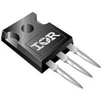
N CHANNEL MOSFET, 600V, 22A, TO-247
Manufacturer
Vishay
Datasheet
1.IRFP22N60KPBF.pdf
(8 pages)
Specifications of IRFP22N60K
Transistor Polarity
N Channel
Continuous Drain Current Id
22A
Drain Source Voltage Vds
600V
On Resistance Rds(on)
280mohm
Rds(on) Test Voltage Vgs
10V
Threshold Voltage Vgs Typ
5V
Configuration
Single
Resistance Drain-source Rds (on)
0.28 Ohms
Drain-source Breakdown Voltage
600 V
Gate-source Breakdown Voltage
+/- 30 V
Continuous Drain Current
22 A
Power Dissipation
370 W
Maximum Operating Temperature
+ 150 C
Mounting Style
Through Hole
Package / Case
TO-247AC
Minimum Operating Temperature
- 55 C
Lead Free Status / RoHS Status
Contains lead / RoHS non-compliant
Available stocks
Company
Part Number
Manufacturer
Quantity
Price
Company:

Part Number:
IRFP22N60K
Manufacturer:
IR
Quantity:
6 000
Company:
Part Number:
IRFP22N60K
Manufacturer:
IR
Quantity:
12 500
Part Number:
IRFP22N60K
Manufacturer:
IR
Quantity:
20 000
Company:
Part Number:
IRFP22N60KPBF
Manufacturer:
IR
Quantity:
77


IRFP22N60K, SiHFP22N60K
Vishay Siliconix
Notes
a. Repetitive rating; pulse width limited by maximum junction temperature (see fig. 11).
b. Pulse width ≤ 300 µs; duty cycle ≤ 2 %.
c. C
www.vishay.com
2
THERMAL RESISTANCE RATINGS
PARAMETER
Maximum Junction-to-Ambient
Case-to-Sink, Flat, Greased Surface
Maximum Junction-to-Case (Drain)
SPECIFICATIONS T
PARAMETER
Static
Drain-Source Breakdown Voltage
V
Gate-Source Threshold Voltage
Gate-Source Leakage
Zero Gate Voltage Drain Current
Drain-Source On-State Resistance
Forward Transconductance
Dynamic
Input Capacitance
Output Capacitance
Reverse Transfer Capacitance
Output Capacitance
Effective Output Capacitance
Total Gate Charge
Gate-Source Charge
Gate-Drain Charge
Turn-On Delay Time
Rise Time
Turn-Off Delay Time
Fall Time
Drain-Source Body Diode Characteristics
Continuous Source-Drain Diode Current
Pulsed Diode Forward Current
Body Diode Voltage
Body Diode Reverse Recovery Time
Body Diode Reverse Recovery Charge
Reverse Recovery Current
Forward Turn-On Time
DS
oss
Temperature Coefficient
eff. is a fixed capacitance that gives the same charging time as C
J
a
= 25 °C, unless otherwise noted
SYMBOL
SYMBOL
ΔV
C
R
V
oss
t
t
I
I
I
C
C
R
R
V
C
V
R
GS(th)
DS(on)
C
Q
Q
d(on)
d(off)
I
RRM
GSS
DSS
Q
g
Q
t
DS
SM
I
t
t
on
thCS
DS
oss
oss
t
SD
thJA
thJC
iss
rss
S
rr
gd
fs
gs
r
f
g
rr
eff.
/T
J
MOSFET symbol
showing the
integral reverse
p - n junction diode
T
T
V
V
T
T
V
J
J
V
GS
GS
J
J
GS
= 125 °C
=1 25 °C
DS
T
= 25 °C
= 25 °C
Intrinsic turn-on time is negligible (turn-on is dominated by L
Reference to 25 °C, I
= 10 V
= 10 V
J
= 0 V
= 480 V, V
= 25 °C, I
V
V
V
V
V
f = 1.0 MHz, see fig. 5
R
TYP.
TEST CONDITIONS
0.24
DS
DS
DD
GS
oss
DS
G
-
-
= 600 V, V
= V
= 300 V, I
= 6.2, V
= 0 V, I
= 50 V, I
V
while V
V
see fig. 10
V
T
GS
V
V
DS
S
GS
J
GS
DS
GS
I
DS
D
= 22 A, V
= 25 °C
= ± 30 V
, I
= 25 V,
V
= 0 V,
= 22 A, V
see fig. 6 and 13
= 480 V , f = 1.0 MHz
dI/dt = 100 A/µs
= 0 V, T
= 1.0 V , f = 1.0 MHz
DS
D
D
GS
DS
D
= 250 µA
= 250 µA
D
I
= 0 V to 480 V
GS
I
= 10 V,
D
= 13 A
is rising from 0 to 80 % V
F
= 22 A,
b
D
= 13 A
= 22 A,
= 0 V
GS
= 1 mA
J
DS
G
= 125 °C
= 0 V
b
= 480 V
b
d
b
MAX.
b
b
0.34
D
S
40
-
MIN.
600
3.0
11
-
-
-
-
-
-
-
-
-
-
-
-
-
-
-
-
-
-
-
-
-
-
-
-
-
-
DS
.
S-81274-Rev. A, 16-Jun-08
Document Number: 91208
0.240
TYP.
3570
4710
0.30
350
180
590
670
7.2
8.5
36
92
26
99
48
37
26
-
-
-
-
-
-
-
-
-
-
-
-
UNIT
°C/W
± 100
MAX.
0.280
1010
S
250
150
890
5.0
1.5
50
45
76
22
88
11
13
39
-
-
-
-
-
-
-
-
-
-
-
-
-
and L
D
UNIT
)
V/°C
nA
µA
nC
µC
pF
ns
ns
V
V
Ω
S
A
V
Related parts for IRFP22N60K
Image
Part Number
Description
Manufacturer
Datasheet
Request
R

Part Number:
Description:
357-036-542-201 CARDEDGE 36POS DL .156 BLK LOPRO
Manufacturer:
Vishay
Datasheet:
Part Number:
Description:
357-036-542-201 CARDEDGE 36POS DL .156 BLK LOPRO
Manufacturer:
Vishay
Datasheet:
Part Number:
Description:
357-036-542-201 CARDEDGE 36POS DL .156 BLK LOPRO
Manufacturer:
Vishay
Datasheet:
Part Number:
Description:
357-036-542-201 CARDEDGE 36POS DL .156 BLK LOPRO
Manufacturer:
Vishay
Datasheet:
Part Number:
Description:
357-036-542-201 CARDEDGE 36POS DL .156 BLK LOPRO
Manufacturer:
Vishay
Datasheet:
Part Number:
Description:
357-036-542-201 CARDEDGE 36POS DL .156 BLK LOPRO
Manufacturer:
Vishay
Datasheet:
Part Number:
Description:
357-036-542-201 CARDEDGE 36POS DL .156 BLK LOPRO
Manufacturer:
Vishay
Datasheet:
Part Number:
Description:
357-036-542-201 CARDEDGE 36POS DL .156 BLK LOPRO
Manufacturer:
Vishay
Datasheet:
Part Number:
Description:
357-036-542-201 CARDEDGE 36POS DL .156 BLK LOPRO
Manufacturer:
Vishay
Datasheet:
Part Number:
Description:
357-036-542-201 CARDEDGE 36POS DL .156 BLK LOPRO
Manufacturer:
Vishay
Datasheet:
Part Number:
Description:
357-036-542-201 CARDEDGE 36POS DL .156 BLK LOPRO
Manufacturer:
Vishay
Datasheet:
Part Number:
Description:
357-036-542-201 CARDEDGE 36POS DL .156 BLK LOPRO
Manufacturer:
Vishay
Datasheet:
Part Number:
Description:
357-036-542-201 CARDEDGE 36POS DL .156 BLK LOPRO
Manufacturer:
Vishay
Datasheet:
Part Number:
Description:
357-036-542-201 CARDEDGE 36POS DL .156 BLK LOPRO
Manufacturer:
Vishay
Datasheet:
Part Number:
Description:
357-036-542-201 CARDEDGE 36POS DL .156 BLK LOPRO
Manufacturer:
Vishay
Datasheet: