AFBR-0978Z Avago Technologies US Inc., AFBR-0978Z Datasheet - Page 5
AFBR-0978Z
Manufacturer Part Number
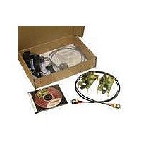
AFBR-0978Z
Description
650nm FE Transceiver Eval Kit
Manufacturer
Avago Technologies US Inc.
Specifications of AFBR-0978Z
Main Purpose
Interface, Ethernet
Embedded
No
Utilized Ic / Part
AFBR-5978Z
Primary Attributes
Supports 10Mbps & 100Mbps
Secondary Attributes
DMI Alarm
Description/function
Evaluation Kit
Operating Voltage
5 V
Lead Free Status / RoHS Status
Contains lead / RoHS non-compliant
For Use With/related Products
AFBR-5978Z
Lead Free Status / RoHS Status
Contains lead / RoHS non-compliant, Lead free / RoHS Compliant
Other names
516-2135
AFBR-0978Z
AFBR-0978Z


Digital Diagnostics Monitoring Interface
The AFBR-5978Z transceiver features an enhanced digital
diagnostic interface, compliant to the “Digital Diagnostic
Monitoring Interface for Optical Transceivers” SFF-8472
Multi-source Agreement (MSA). Please refer to the MSA
document to access information on the range of options,
both hardware and software, available to the host system
for exploiting the available digital diagnostic features.
The enhanced digital interface allows real-time access
to device operating parameters, and includes optional
digital features such as soft control and monitoring of I/O
signals. In addition, it fully incorporates the functionality
needed to implement digital alarms and warnings, as
defined by the SFF-8472 MSA. With the digital diagnostic
monitoring interface, the user has capability of perform-
ing component monitoring, fault isolation and failure
prediction in their transceiver-based applications.
127
Figure 5. Digital diagnostic memory map – specific data field description (from
SFF-8472 MSA)
255
95
0
2 wire address 1010000X (A0h)
SFP MSA (96 bytes)
Serial ID Defined by
Reserved in SFP
MSA (128 bytes)
Vendor Specific
(32 bytes)
119
127
247
255
55
0
2 wire address 1010001X (A2h)
EEPROM (120 bytes)
Vendor Specific (8 bytes)
Thresholds (56 bytes)
Vendor Specific (8 bytes)
Interface (24 bytes)
Alarm and Warning
User Writable
Cal Constants
Time Diagnostic
(40 bytes)
The diagnostic monitoring interface (DMI) has two 256
byte memory maps in EEPROM which are accessible over
a two wire interface: the serial ID memory map at address
1010000X (0xA0) and the digital diagnostic memory map
at address 1010001X (0xA2).
The serial ID memory map contains a serial identification
and vendor specific information and is read only.
The digital diagnostic memory map contains device
operating parameters and alarm and warning flags.
The operating parameters are to be retrieved through
a sequential read command ensuring that the MSB and
LSB of each parameter are “coherent”. Furthermore, it
contains 120 bytes that can be written by the user as well
as a writable soft control byte.
Tables 1 to 6 detail memory contents, timing characteris-
tics, soft commands and alarm/warning flags.
Related parts for AFBR-0978Z
Image
Part Number
Description
Manufacturer
Datasheet
Request
R

Part Number:
Description:
TXRX ETHERNET 125MBD MMF 2X5
Manufacturer:
Avago Technologies US Inc.
Datasheet:

Part Number:
Description:
TXRX OPT XFP 10GB/S 850NM
Manufacturer:
Avago Technologies US Inc.
Datasheet:

Part Number:
Description:
TXRX OPT 1X9 100MBPS DUPLEX SC
Manufacturer:
Avago Technologies US Inc.
Datasheet:

Part Number:
Description:
TXRX OPT 1X9 100MBPS DUPLEX ST
Manufacturer:
Avago Technologies US Inc.
Datasheet:

Part Number:
Description:
TXRX OPT 1X9 100MBPS DUPL ST SIP
Manufacturer:
Avago Technologies US Inc.
Datasheet:

Part Number:
Description:
TXRX OPT 1X9 100MBPS DUPL SC SIP
Manufacturer:
Avago Technologies US Inc.
Datasheet:

Part Number:
Description:
TXRX OPT 1X9 100MBPS DUPL ST SIP
Manufacturer:
Avago Technologies US Inc.
Datasheet:

Part Number:
Description:
TXRX ATM SONET OC3 3V SC 1X9
Manufacturer:
Avago Technologies US Inc.
Datasheet:
Part Number:
Description:
TXRX ATM/SONET OC-3 2X5
Manufacturer:
Avago Technologies US Inc.
Datasheet:

Part Number:
Description:
TXRX 127MBD DUPLEX SC 1X9
Manufacturer:
Avago Technologies US Inc.
Datasheet:

Part Number:
Description:
OPTOCOUPLER GATE DRV 2A 16-SOIC
Manufacturer:
Avago Technologies US Inc.
Datasheet:
Part Number:
Description:
OPTOCOUPLER 2CH 2.5A 16-SOIC
Manufacturer:
Avago Technologies US Inc.
Datasheet:

Part Number:
Description:
OPTOCOUPLER GATE DRV 0.4A 16SOIC
Manufacturer:
Avago Technologies US Inc.
Datasheet:

Part Number:
Description:
OPTOCOUPLER 2.0A 250KHZ 8-DIP
Manufacturer:
Avago Technologies US Inc.
Datasheet:

Part Number:
Description:
OPTOCOUPLER 2.0A 250KHZ GW 8-SMD
Manufacturer:
Avago Technologies US Inc.
Datasheet: