AFBR-0978Z Avago Technologies US Inc., AFBR-0978Z Datasheet - Page 2
AFBR-0978Z
Manufacturer Part Number
AFBR-0978Z
Description
650nm FE Transceiver Eval Kit
Manufacturer
Avago Technologies US Inc.
Specifications of AFBR-0978Z
Main Purpose
Interface, Ethernet
Embedded
No
Utilized Ic / Part
AFBR-5978Z
Primary Attributes
Supports 10Mbps & 100Mbps
Secondary Attributes
DMI Alarm
Description/function
Evaluation Kit
Operating Voltage
5 V
Lead Free Status / RoHS Status
Contains lead / RoHS non-compliant
For Use With/related Products
AFBR-5978Z
Lead Free Status / RoHS Status
Contains lead / RoHS non-compliant, Lead free / RoHS Compliant
Other names
516-2135
AFBR-0978Z
AFBR-0978Z


AFBR-0978Z Circuit Design
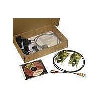
The evaluation board (Figure 1) is based on the reference
design for the AFBR-5978Z transceiver (see application
note 5289).
The data signal from the twisted pair medium is routed
through magnetics to the media converter IC ML6652
input pins (TPINP and TPINN); a 100 W resistor provides the
termination. The transmitter outputs of the ML6652 (IOUT
and IOUT#) are directly connected, over a 50 W transmis-
sion line, to the input of the transceiver with a pull-up
resistor of 75 W to Vcc, which is placed close to the trans-
ceiver. No external capacitor is required since the TD and
TD inputs of the transceiver are internally AC coupled.
The data signal is routed over a 50 W transmission line
from the transceiver RD and RD outputs to the input pins
of the ML6652 (FOINP and FOINN). These LVPECL inputs
are internally biased and need to be AC coupled. The
AFBR-5978Z datasheet states in the functional I/O section
that when AC coupling is used, the LVPECL outputs of
the transceiver have to be pulled to ground before the
AC coupling to DC bias the output. This is achieved by
use of a bias resistor of 160 W. The twisted pair outputs
of the ML6652 (TPOUTP and TPOUTN) are a differential
current output pair that drives the data signal through the
magnetics into the twisted pair medium. Both outputs are
pulled up to Vcc by a 50 W resistor.
Table 1. Function descriptions and switch settings for DIP switches S2 and S3
2
S2
Function
Twisted Pair output ON
Twisted Pair output OFF
Fiber Optic output ON
Fiber Optic output OFF
Link Integrity Warning mode enabled
(works only if media converter is set in
Forced 10 or 100 Mbps mode)
Link Integrity Warning mode disabled
(default)
Switch
1
1
2
2
3
4
3
4
State
OFF
ON
OFF
ON
ON
OFF
OFF
ON
Board Power
The supplied 5 V power adapter is connected to the
board by a DC plug and is suitable for 220 V/50 Hz or
110 V/60 Hz outlets. Note that this power adapter does
not ground the board to earth. To avoid damage to mea-
surement equipment connected to the board or incorrect
measurement results, make sure the evaluation board is
connected to ground. Connecting one of the I/O ground
pins or the DC plug ground pin to earth accomplishes
this.
Initial Setup
The twisted pair interface (RJ-45 port) is conFigured in
a straight-through mode. If the evaluation kit is used to
link two Ethernet devices, one of these devices should be
a hub or switch. Otherwise one cross-over cable needs to
be used to complete the link.
To get started it is recommended to set-up both AFBR-
0978Z boards in the “transparent with auto-negotiation”
mode. This is established by setting S2: 1-OFF, 2-OFF,
3-OFF, 4-ON and setting S3: all OFF. See table 1 for other
settings.
Once the hardware configuration has been set, the AFBR-
0978Z evaluation board is ready to be incorporated in the
Ethernet (test) environment.
S3
Function
Forced 10 Mbps mode
(auto-negotiation is off, duplex mode is
selected by link partners)
Forced 100 Mbps mode
(auto-negotiation is off, duplex mode is
selected by link partners)
Non-transparent half duplex auto-
negotiation
(for FO partner without auto-negotiation,
only half duplex is advertised)
Non-transparent auto-negotiation
(for FO partner without auto-negotiation)
Transparent with auto-negotiation
(suitable when both FO and TP partners
support auto-negotiation)
Switch
1
2
3
4
1
2
3
4
1
2
3
4
1
2
3
4
1
2
3
4
State
OFF
ON
OFF
OFF
ON
OFF
OFF
OFF
OFF
OFF
ON
OFF
OFF
OFF
OFF
ON
OFF
OFF
OFF
OFF
Related parts for AFBR-0978Z
Image
Part Number
Description
Manufacturer
Datasheet
Request
R

Part Number:
Description:
TXRX ETHERNET 125MBD MMF 2X5
Manufacturer:
Avago Technologies US Inc.
Datasheet:

Part Number:
Description:
TXRX OPT XFP 10GB/S 850NM
Manufacturer:
Avago Technologies US Inc.
Datasheet:

Part Number:
Description:
TXRX OPT 1X9 100MBPS DUPLEX SC
Manufacturer:
Avago Technologies US Inc.
Datasheet:

Part Number:
Description:
TXRX OPT 1X9 100MBPS DUPLEX ST
Manufacturer:
Avago Technologies US Inc.
Datasheet:

Part Number:
Description:
TXRX OPT 1X9 100MBPS DUPL ST SIP
Manufacturer:
Avago Technologies US Inc.
Datasheet:

Part Number:
Description:
TXRX OPT 1X9 100MBPS DUPL SC SIP
Manufacturer:
Avago Technologies US Inc.
Datasheet:

Part Number:
Description:
TXRX OPT 1X9 100MBPS DUPL ST SIP
Manufacturer:
Avago Technologies US Inc.
Datasheet:

Part Number:
Description:
TXRX ATM SONET OC3 3V SC 1X9
Manufacturer:
Avago Technologies US Inc.
Datasheet:
Part Number:
Description:
TXRX ATM/SONET OC-3 2X5
Manufacturer:
Avago Technologies US Inc.
Datasheet:

Part Number:
Description:
TXRX 127MBD DUPLEX SC 1X9
Manufacturer:
Avago Technologies US Inc.
Datasheet:

Part Number:
Description:
OPTOCOUPLER GATE DRV 2A 16-SOIC
Manufacturer:
Avago Technologies US Inc.
Datasheet:
Part Number:
Description:
OPTOCOUPLER 2CH 2.5A 16-SOIC
Manufacturer:
Avago Technologies US Inc.
Datasheet:

Part Number:
Description:
OPTOCOUPLER GATE DRV 0.4A 16SOIC
Manufacturer:
Avago Technologies US Inc.
Datasheet:

Part Number:
Description:
OPTOCOUPLER 2.0A 250KHZ 8-DIP
Manufacturer:
Avago Technologies US Inc.
Datasheet:

Part Number:
Description:
OPTOCOUPLER 2.0A 250KHZ GW 8-SMD
Manufacturer:
Avago Technologies US Inc.
Datasheet: