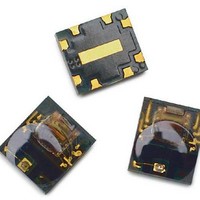
AEDR-8500-100 Avago Technologies US Inc., AEDR-8500-100 Datasheet - Page 7

AEDR-8500-100
Manufacturer Part Number
AEDR-8500-100
Description
IC,Gt90e,Reel,304LPI,1000pc
Manufacturer
Avago Technologies US Inc.
Datasheet
1.AEDR-8501-102.pdf
(9 pages)
Specifications of AEDR-8500-100
Number Of Channels
3
Mounting Style
SMD/SMT
Output
Incremental
Supply Voltage
7 V
Operating Temperature Range
- 20 C to + 85 C
Product
Optical
No. Of Channels
3
Supply Voltage Range
4.5V To 5.5V
Encoder Type
Incremental
Sensor Supply Voltage
4.5V To 5.5V
Lead Free Status / Rohs Status
Lead free / RoHS Compliant
Direction of Movement
With the
B when the codewheel rotates anti-clockwise and vice versa (with the encoder mounted on top of the codewheel).
The optimal gap setting recommended is between 0.5 mm to 1 mm (See side view below).
7
Encoder Placement Orientation and Positioning
The AEDR-850X is designed such that both the emitter and detector IC should be placed parallel to the window/bar
orientation, as shown (with the encoder mounted on top of the codewheel. See view below).
Most importantly,
(R
Codewheel
Ch. A leads
Ch. B
OP
) or rather the center point of Lw (0.5 of the Length of Window). Lw is recommended to be 1.8 mm or greater.
detector side of the encoder placed closer to the codewheel centre
the center of the lens
Emitter
Codewheel
Anti-clockwise
Encoder height = 0.9562 mm
of the encoder unit; needs to be in line with the operating radius of the codewheel
Note: Drawing not to scale.
Gap = 0.5 to 1 mm
Side View
Top View
Top View
Codewheel
Codewheel
Ch. B leads
Ch. A
Emitter
, see the above top view; Channel A leads Channel
Detector
Emitter
the encoder’s on the codewheel
Note: Drawing not to scale
Placement orientation of
Codewheel
Clockwise


