HFBR-2416T Avago Technologies US Inc., HFBR-2416T Datasheet - Page 9
HFBR-2416T
Manufacturer Part Number
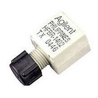
HFBR-2416T
Description
Fiber Optics, Transceiver Module
Manufacturer
Avago Technologies US Inc.
Datasheet
1.HFBR-2416T.pdf
(24 pages)
Specifications of HFBR-2416T
Data Rate Max
115Kbps
Peak Reflow Compatible (260 C)
No
Leaded Process Compatible
No
Data Transmission Distance
2700ft
Lead Free Status / RoHS Status
Contains lead / RoHS non-compliant
Available stocks
Company
Part Number
Manufacturer
Quantity
Price
Company:

Part Number:
HFBR-2416T
Manufacturer:
AGILENT
Quantity:
16
Part Number:
HFBR-2416T
Manufacturer:
HP
Quantity:
20 000
Part Number:
HFBR-2416TC
Manufacturer:
HP
Quantity:
20 000
Company:
Part Number:
HFBR-2416TCZ
Manufacturer:
Avago Technologies US Inc.
Quantity:
135
Company:
Part Number:
HFBR-2416TZ
Manufacturer:
BROTHER
Quantity:
16 250
Part Number:
HFBR-2416TZ
Manufacturer:
AVAGO/安华高
Quantity:
20 000


Description
The following technical data is
taken from 4 popular links using
the HFBR-0400 series: the 5 MBd
link, Ethernet 20 MBd link,
Token Ring 32 MBd link, and the
155 MBd link. The data given
9
Typical Link Data
5 MBd Link (HFBR-14XX/24X2)
Link Performance -40 C to +85 C unless otherwise specified
Notes:
1. OPB at T
2. Synchronous data rate limit is based on these assumptions: a) 50% duty factor modulation, e.g., Manchester I or BiPhase Manchester II; b)
3. Asynchronous data rate limit is based on these assumptions: a) NRZ data; b) arbitrary timing-no duty factor restriction; c) TTL threshold.
HFBR-0400 Series
Parameter
Optical Power Budget
with 50/125 m fiber
Optical Power Budget
with 62.5/125 m fiber
Optical Power Budget
with 100/140 m fiber
Optical Power Budget
with 200 m fiber
Date Rate Synchronous
Asynchronous
Propagation Delay
LOW to HIGH
Propagation Delay
HIGH to LOW
System Pulse Width
Distortion
Bit Error Rate
continuous data; c) PLL Phase Lock Loop demodulation; d) TTL threshold.
A
= -40 to 85 C, V
CC
= 5.0 V dc, I
Symbol
OPB
OPB
OPB
OPB
t
t
t
BER
PLH
PHL
PLH
F ON
-t
50
62.5
100
200
PHL
= 60 mA. P
corresponds to transceiver solu-
tions combining the HFBR-0400
series components and various
recommended transceiver design
circuits using off-the-shelf
electrical components. This data
is meant to be regarded as an
Min.
4.2
8.0
8.0
12
dc
dc
R
= -24 dBm peak.
Typ.
9.6
15
15
20
72
46
26
Max.
5
2.5
10
-9
Units
dB
dB
dB
dB
MBd
MBd
ns
ns
ns
Conditions
HFBR-14X4/24X2
NA = 0.2
HFBR-14X4/24X2
NA = 0.27
HFBR-14X2/24X2
NA = 0.30
HFBR-14X2/24X2
NA = 0.37
T
P
Fiber cable
length = 1 m
Data Rate <5 Bd
P
A
example of typical link perform-
ance for a given design and does
not call out any link limitations.
Please refer to the appropriate
application note given for each
link to obtain more information.
R
R
= 25 C,
= -21 dBm Peak
> -24 dBm Peak
Reference
Note 1
Note 1
Note 1
Note 1
Note 2
Note 3,
Fig. 7
Figs. 6, 7, 8
Related parts for HFBR-2416T
Image
Part Number
Description
Manufacturer
Datasheet
Request
R

Part Number:
Description:
FIBER OPTIC CONN LATCH GRY SIMPL
Manufacturer:
Avago Technologies US Inc.
Datasheet:

Part Number:
Description:
FIBER OPTIC CONN LATCH BLU SIMPL
Manufacturer:
Avago Technologies US Inc.
Datasheet:

Part Number:
Description:
FIBER OPTIC CRIMPLESS CONN GRAY
Manufacturer:
Avago Technologies US Inc.
Datasheet:

Part Number:
Description:
FIBER OPTIC CONN BLUE SIMPLEX
Manufacturer:
Avago Technologies US Inc.
Datasheet:

Part Number:
Description:
FIBER OPTIC CONN LATCH DUPLEX
Manufacturer:
Avago Technologies US Inc.
Datasheet:

Part Number:
Description:
FIBER OPTIC CONN DUPLEX
Manufacturer:
Avago Technologies US Inc.
Datasheet:

Part Number:
Description:
FIBER OPTIC CONN GRAY SIMPLEX
Manufacturer:
Avago Technologies US Inc.
Datasheet:

Part Number:
Description:
FIBER OPTIC CBL DUPLEX 1=100M
Manufacturer:
Avago Technologies US Inc.
Datasheet:

Part Number:
Description:
FIBER OPTIC CBL DUPLEX 1=500M
Manufacturer:
Avago Technologies US Inc.
Datasheet:

Part Number:
Description:
FIBER OPTIC CBL CONN DUPLEX 5M
Manufacturer:
Avago Technologies US Inc.
Datasheet:

Part Number:
Description:
OPTOCOUPLER GATE DRV 2A 16-SOIC
Manufacturer:
Avago Technologies US Inc.
Datasheet:
Part Number:
Description:
OPTOCOUPLER 2CH 2.5A 16-SOIC
Manufacturer:
Avago Technologies US Inc.
Datasheet:

Part Number:
Description:
OPTOCOUPLER GATE DRV 0.4A 16SOIC
Manufacturer:
Avago Technologies US Inc.
Datasheet:

Part Number:
Description:
OPTOCOUPLER 2.0A 250KHZ 8-DIP
Manufacturer:
Avago Technologies US Inc.
Datasheet:

Part Number:
Description:
OPTOCOUPLER 2.0A 250KHZ GW 8-SMD
Manufacturer:
Avago Technologies US Inc.
Datasheet: