HSMH-C265 Avago Technologies US Inc., HSMH-C265 Datasheet
HSMH-C265
Specifications of HSMH-C265
Available stocks


Related parts for HSMH-C265


HSMH-C265 Summary of contents
Page 1
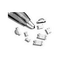
... HSMD-Cxxx, HSMG-Cxxx, HSMH-Cxxx, HSMS-Cxxx, HSMY-Cxxx, Surface Mount Chip LEDs Data Sheet HSMx-C110/ HSMx-C120/HSMx-C150/HSMx-C170/HSMx-C177/ HSMx-C190/HSMx-C191/HSMx-C197/HSMx-C265 Description These chip LEDs are designed in an industry standard package for ease of handling and use. Various different LED colors are available in nine compact, single color packages. The HSMx-C150 has the industry standard 3.2 x 1.6 mm footprint that is excellent for all around use ...
Page 2
... HSMG-C191 HSMS-C191 HSMG-C197 HSMS-C197 HSMG-C265 – As AlGaAs Red HSMH-C110 HSMH-C120 HSMH-C150 HSMH-C170 HSMH-C190 HSMH-C191 HSMH-C265 Package Dimensions 3.2 (0.126 ) DIFFUSED 2.0 (0.079) EPOXY 0.6 (0.024) PC BOARD CATHODE LINE (ANODE LINE 0.5 (0.020) FOR HSMH-C150) 0.50 ± 0.2 (0.020 ± 0.008) ...
Page 3
... SOLDERING TERMINAL HSMx-C191 Notes: 1. All dimensions in millimeters (inches). 2. Tolerance is ±0.1 mm (±0.004 in.) unless otherwise specified. 3. Polarity for HSMH-Cxxx will be the opposite of what is shown on above drawings. 3 0.8 (0.031) CLEAR EPOXY [3] POLARITY PC BOARD 0.8 (0.031) CATHODE MARK 0 ...
Page 4
... HSMx-C120 Notes: 1. All dimensions in millimeters (inches). 2. Tolerance is ±0.1 mm (±0.004 in.) unless otherwise specified. 3. Polarity for HSMH-Cxxx will be the opposite of what is shown on above drawings. 4 CATHODE MARK (ETCHED) [ANODE MARK FOR HSMH-C265] 1.25 (0.049) [3] POLARITY DIFFUSED 1.1 (0.043) PC BOARD 0.50 ± 0.15 (0.012 ± 0.006) (0.020 ± ...
Page 5
... Derate linearly as shown in Figure 4 for temperature above 25°C. Electrical Characteristics at T =25°C A Part Number HSMS-C110/150 HSMS-C120 HSMS-C170/177/190/191/197 HSMD-C110/150 HSMD-C120 HSMD-C170/177/190/191/197 HSMY-C110/150 HSMY-C170/177/190/191/197 HSMG-C110/150 HSMG-C120 HSMG-C170/177/190191/197/265 HSMH-C110/150 HSMH-C120 HSMH-C170/190/191/265 5 =25°C A C110/150/265 C120/170/177/190/191/197 -40 to +85 -40 to +85 See reflow soldering profile (Figure 9 & 10) =25°C A C110/150 30 65 ...
Page 6
... HSMD-C120 HSMD-C150/170/190/191 HSMY-C110/177/197 HSMY-C150/170/190/191 HSMH-C110 HSMH-C120 HSMH-C150/170/190/191/265 Notes: 1. The luminous intensity, Iv, is measured at the peak of the spatial radiation pattern, which may not be aligned with the mechanical axis of the lamp package the off-axis angle where the luminous intensity is 1/2 the peak intensity. ...
Page 7
Light Intensity (Iv) Bin Limits Intensity (mcd) Bin ID Min. Max. A 0.11 0.18 B 0.18 0.29 C 0.29 0.45 D 0.45 0.72 E 0.72 1.10 F 1.10 1.80 G 1.80 2.80 H 2.80 4.50 J 4.50 7.20 K ...
Page 8
ANGLE 1.00 0.90 0.80 0.70 0.60 0.50 0.40 0.30 0.20 0.10 0 -90 -80 -70 -60 -50 -40 -30 ...
Page 9
ANGLE Figure 7. Relative intensity vs. angle for HSMx-C177 and C197. 1.00 0.90 0.80 0.70 0.60 0.50 0.40 0.30 ...
Page 10
Figure 14. Recommended soldering pattern for HSMx-C110. 2.2 (0.087) DIA. PCB HOLE 1.4 2.3 1.4 (0.055) (0.091) (0.055) Figure 16. Recommended soldering pattern for HSMx-C265. 3.0 ...
Page 11
DIM. A (SEE TABLE 1) DIM. B (SEE TABLE 1) 2.00 ± 0.05 (0.079 ± 0.002) 4.00 (0.157) HSMx-C110/C120 POSITION IN CARRIER TAPE DIM. A (SEE TABLE 1) R 1.0 ± 0.05 DIM. B (0.039 ± 0.002) (SEE ...
Page 12
END THERE SHALL BE A MOUNTED WITH MINIMUM OF 160 mm COMPONENTS (6.3 INCH) OF EMPTY COMPONENT POCKETS SEALED WITH COVER TAPE. Figure 20. Tape leader and trailer dimensions. Notes: 1. All dimensions in millimeters (inches). 2. Tolerance is ±0.1 ...