EB018 MATRIX, EB018 Datasheet - Page 7
EB018
Manufacturer Part Number
EB018
Description
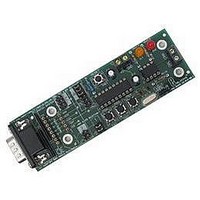
E-blocks CAN Bus Board
Manufacturer
MATRIX
Datasheet
1.EB018.pdf
(9 pages)
Specifications of EB018
Silicon Manufacturer
Matrix
Application Sub Type
CAN Bus
Kit Application Type
Interface
Silicon Core Number
MCP2515 And MCP2551
Kit Contents
Board
Rohs Compliant
Yes
Lead Free Status / RoHS Status
Lead free / RoHS Compliant


5. Circuit description
1. CAN Controller – MCP2515
2. CAN Transceiver – MCP2551
The circuit as can be seen in the circuit diagram below (See Appendix 1 – Circuit diagram), is made up of two main
components: the CAN Controller (MCP2515) and the CAN Transceiver (MCP2551).
The MCP 2515 CAN Controller enables the user to add a CAN bus a system where CAN is not already embedded
into the processor. The device uses the high speed SPI protocol to configure the CAN controller to allow the system
to transmit and receive CAN messages.
The MCP2515 provides masks and filters that can filter away messages that are not wanted. Both standard and
extended frames are implemented, including remote frames, as is Data byte filtering of the first two data bytes.
The device has 3 dedicated Inputs, which are connected to 3 input switches on the CAN board (IN1, IN2 and IN3).
These switches can also be configured as Request-To-Send pins, which allow the user to manually request
transmission of each transmit buffer.
There are also 2 dedicated outputs. These are connected to LEDs D1 and D2. The pins connected to the LEDs can
be configured as buffer-full indicators indicating that message has been successfully received.
Users will need to consult the MCP2515 datasheet for information on programming and using this device. The
datasheet for this can be found on the Microchip website at:
The MCP2551 CAN transceiver is an interface between the CAN controller and the CAN bus. It converts the logic
levels of the CAN controller and the differential signals levels of the CAN bus. It will also convert from the CAN
bus signals to TTL logic level for the CAN controller.
The CAN_H and CAN_L outputs are connected to the screw terminal J2. Also there is a link block (J8) that allows
the user to determine if this CAN node is the end terminal, by adding a termination resistor. As can be seen in the
diagram below, the two outer CAN boards have the link block for J8 in the “END NODE” position. The middle
CAN board has the link in the other position to indicate that is not an end node.
Copyright © Matrix Multimedia Limited 2005
For more information please look at the datasheet for this device which can be found at:
CAN bus diagram showing “End nodes” in use.
www.microchip.com
E-blocks™ CAN bus board
Document code: EB018-30-1
www.microchip.com
page 7
Related parts for EB018
Image
Part Number
Description
Manufacturer
Datasheet
Request
R


Part Number:
Description:
MATRIX CARD FOR HI-LO PROG
Manufacturer:
Cypress Semiconductor Corp
Part Number:
Description:
MATRIX CARD FOR HI-LO PROG
Manufacturer:
Cypress Semiconductor Corp
Datasheet:
Part Number:
Description:
MATRIX CARD FOR HI-LO PROG
Manufacturer:
Cypress Semiconductor Corp
Datasheet:
Part Number:
Description:
MATRIX CARD FOR HI-LO PROG
Manufacturer:
Cypress Semiconductor Corp
Datasheet:
Part Number:
Description:
MATRIX CARD FOR HI-LO PROG
Manufacturer:
Cypress Semiconductor Corp
Part Number:
Description:
MATRIX CARD FOR HI-LO PROG
Manufacturer:
Cypress Semiconductor Corp
Part Number:
Description:
MATRIX CARD FOR HI-LO PROG
Manufacturer:
Cypress Semiconductor Corp
Datasheet:
Part Number:
Description:
MATRIX CARD FOR HI-LO PROG
Manufacturer:
Cypress Semiconductor Corp

Part Number:
Description:
Color Video Chrominance Signal Processing Circuit
Manufacturer:
Matrix Orbital.
Datasheet:
Part Number:
Description:
Recording Video Signal Processing Circuit
Manufacturer:
Matrix Orbital.
Datasheet:
Part Number:
Description:
Driver Circuit
Manufacturer:
Matrix Orbital.
Datasheet: