KIT3376MMA7361LC Freescale Semiconductor, KIT3376MMA7361LC Datasheet - Page 5
KIT3376MMA7361LC
Manufacturer Part Number
KIT3376MMA7361LC
Description
Analog Output Accelerometer Evaluation Board
Manufacturer
Freescale Semiconductor
Datasheet
1.KIT3376MMA7361LC.pdf
(6 pages)
Specifications of KIT3376MMA7361LC
Silicon Manufacturer
Freescale
Application Sub Type
Accelerometer
Kit Application Type
Sensing - Motion / Vibration / Shock
Silicon Core Number
MMA7360
Acceleration
1.5 g, 6 g
Operating Current
400 uA
Operating Voltage
3.3 V
Output Type
Analog
Sensing Axis
Triple Axis
Sensitivity
800 mV/g to 206 mV/g
Lead Free Status / RoHS Status
Lead free / RoHS Compliant
For Use With/related Products
MMA7361LC
Lead Free Status / RoHS Status
Lead free / RoHS Compliant


Sensors
Freescale Semiconductor
1. Connect the external power source to the Evaluation
2. Turn the side on/off switch into the “on” position as
3. Using a thin pointed tool turn the sleep mode dipswitch
Board. The 3.3V/2.8V input is connected to the + (Vdd)
and Gnd (Vss) using the solder pads.
shown in
the accelerometer and helps preserve battery life if a
battery is being used as the power source. Therefore
SW1 must be set toward the “on” position for the
accelerometer to function.
(SW2) to the “on” position as shown in
can also power the sleep mode using the solder pad
available. This enables the device. A low signal (0) will
bring the board into sleep mode which puts it in a power
saving mode. In this state there will be no X, Y or Z
outputs on these output solder pads. For normal device
operation though the sleep mode must be in the “on”
Figure
Sleep Mode
Self Test Pushbutton
G-Select
4. The on/off switch provides power to
QUICK START GUIDE: HOW TO USE THE EVALUATION BOARD
On/Off Switch
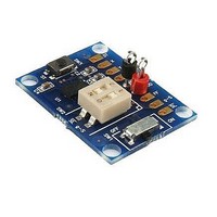
Figure 4. Evaluation Board Components
Figure
4, or you
4. Connect the X, Y and Z outputs to an oscilloscope to
5. The evaluation board has pads for interfacing to a
6. The g-Select is shown in
7. The “FF” solder pad will output a high signal when the
position. This will activate the device showing X, Y and
Z outputs on the X, Y and Z output pads.
view the outputs, or you can also solder these pads to
a microcontroller or any other measuring device.
3.3V/2.8V power source or battery. The pads on the
side of the board also provide a means for connecting
the accelerometer analog output by soldering a wire
from the evaluation board to another breadboard or
system.
the two possible g-modes. You can also use the solder
pad “G_S” to access and change the g-mode.
device has detected that X, Y and Z accelerations are
Figure 4
Self Test
X Axis Output
Y Axis Output
Z Axis Output
V
V
0g-Detect
g-Select
Sleep Mode
SS
DD
(SW2) in the lower of
AN3376
5
Related parts for KIT3376MMA7361LC
Image
Part Number
Description
Manufacturer
Datasheet
Request
R

Part Number:
Description:
Manufacturer:
Freescale Semiconductor, Inc
Datasheet:
Part Number:
Description:
Manufacturer:
Freescale Semiconductor, Inc
Datasheet:
Part Number:
Description:
Manufacturer:
Freescale Semiconductor, Inc
Datasheet:
Part Number:
Description:
Manufacturer:
Freescale Semiconductor, Inc
Datasheet:
Part Number:
Description:
Manufacturer:
Freescale Semiconductor, Inc
Datasheet:
Part Number:
Description:
Manufacturer:
Freescale Semiconductor, Inc
Datasheet:
Part Number:
Description:
Manufacturer:
Freescale Semiconductor, Inc
Datasheet:
Part Number:
Description:
Manufacturer:
Freescale Semiconductor, Inc
Datasheet:
Part Number:
Description:
Manufacturer:
Freescale Semiconductor, Inc
Datasheet:
Part Number:
Description:
Manufacturer:
Freescale Semiconductor, Inc
Datasheet:
Part Number:
Description:
Manufacturer:
Freescale Semiconductor, Inc
Datasheet:
Part Number:
Description:
Manufacturer:
Freescale Semiconductor, Inc
Datasheet:
Part Number:
Description:
Manufacturer:
Freescale Semiconductor, Inc
Datasheet:
Part Number:
Description:
Manufacturer:
Freescale Semiconductor, Inc
Datasheet:
Part Number:
Description:
Manufacturer:
Freescale Semiconductor, Inc
Datasheet: