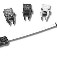
HFBR-0560 Avago Technologies US Inc., HFBR-0560 Datasheet - Page 6

HFBR-0560
Manufacturer Part Number
HFBR-0560
Description
Fiber Optics, Evaluation Kit
Manufacturer
Avago Technologies US Inc.
Datasheet
1.HFBR-0559.pdf
(16 pages)
Specifications of HFBR-0560
Silicon Manufacturer
Avago
Silicon Core Number
HFBR-5903/5903E/5903A
Kit Application Type
Communication & Networking
Application Sub Type
Ethernet Transceiver
Main Purpose
Interface, Ethernet
Embedded
No
Utilized Ic / Part
HFBR-5903, FDDL, Fast Ethernet Transceivers
Primary Attributes
MT-RJ 125Mb/s, Multimode and Singlemode Applications
Secondary Attributes
MT-RJ Fiber Connector Interface
Description/function
Fiber Optic Kit
Lead Free Status / RoHS Status
Lead free / RoHS Compliant
For Use With/related Products
HFCT-5903E
Lead Free Status / RoHS Status
Lead free / RoHS Compliant, Contains lead / RoHS non-compliant
The transceivers may be used for other applications at
signaling rates outside of the 10 MBd to 125 MBd range
with some penalty in the link optical power budget
primarily caused by a reduction of receiver sensitivity.
Figure 5 gives an indication of the typical performance
of these 1300 nm products at different rates.
These transceivers can also be used for applications
which require different Bit Error Rate (BER) performance.
Figure 6 illustrates the typical trade-off between link
BER and the receivers input optical power level.
Transceiver Jitter Performance
The Avago Technologies 1300 nm transceivers are
designed to operate per the system jitter allocations
stated in Table E1 of Annex E of the FDDI PMD and
LCF-PMD standards.
The Avago Technologies 1300 nm transmitters will
tolerate the worst case input electrical jitter allowed in
these tables without violating the worst case output
jitter requirements of Sections 8.1 Active Output
Interface of the FDDI PMD and LCF-PMD standards.
Figure 7. Recommended Decoupling and Termination Circuits
6
Note: C1 = C2 = C3 = 10 nF or 100 nF
TX
RX
10
TRANSCEIVER INPUTS
1
TERMINATE AT
9
2
8
3
130 Ω
100
7
4 5
6
130 Ω
C2
C1
Z = 50 Ω
Z = 50 Ω
1 µH
1 µH
V CC (+3.3 V)
C3
Z = 50 Ω
Z = 50 Ω
Z = 50 Ω
10 µF
Figure 6. Bit Error Rate vs. Relative Receiver Input Optical
Power.
1 x 10 -2
1 x 10 -3
1 x 10 -4
1 x 10 -5
1 x 10 -6
1 x 10 -7
1 x 10 -8
1 x 10 -9
1 x 10 -10
1 x 10 -11
1 x 10 -12
-6
CONDITIONS:
1. 125 MBd
2. PRBS 2
3. CENTER OF SYMBOL SAMPLING
4. T
5. V
6. INPUT OPTICAL RISE/FALL TIMES = 1.0/ 2.1 ns.
RELATIVE INPUT OPTICAL POWER - dB
A
CC
= +25 ˚C
= 3.3 V dc
-4
7
130 Ω
-1
-2
TERMINATE AT
DEVICE INPUTS
130 Ω
HFBR-5903 SERIES
82 Ω
V CC (+3.3V)
100 Ω
130 Ω
CENTER OF SYMBOL
0
2
TD-
TD+
RD+
RD-
SD
4
PHY DEVICE
V CC (+3.3 V)
LVPECL
V CC (+3.3 V)
LVPECL


